Sound output apparatus

Inactive Publication Date: 2018-11-08
MODA INNOCHIPS CO LTD
View PDF0 Cites 15 Cited by
  • Summary
  • Abstract
  • Description
  • Claims
  • Application Information

AI Technical Summary

Benefits of technology

The sound output apparatus described in this patent includes a dynamic speaker and a piezoelectric speaker positioned close to each other in a housing. This arrangement allows for better sound quality in the audio frequency band. Additionally, the piezoelectric speaker has an opening in a specific area, which allows for the mixing of the sounds from both speakers, improving the overall sound quality without compromising the size of the housing. This design also allows for the miniaturization of the earphone.

Problems solved by technology

However, the piezoelectric speaker has a disadvantage in that it has difficulties in listening to music for a long time because it has a strong high-pitched sound and a weak low-pitched sound.
However, the dynamic speaker is appropriate for realizing a low-pitched sound but relatively weak for realizing a high-pitched sound, and thus has a limitation to provide a high quality sound.
However, the sound output apparatus has a limitation in reducing its size.
However, in this case, sound characteristics are degraded.

Method used


Image

  • Sound output apparatus
  • Sound output apparatus
  • Sound output apparatus

Examples


Embodiment Construction

[0053]Hereinafter, specific embodiments will be described in detail with reference to the accompanying drawings. The present disclosure may, however, be embodied in different forms and should not be construed as limited to the embodiments set forth herein. Rather, these embodiments are provided so that this disclosure will be thorough and complete, and will fully convey the scope of the present disclosure to those skilled in the art.

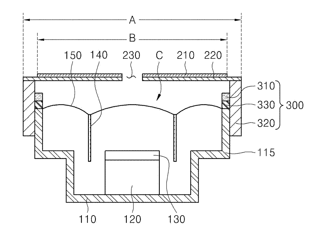
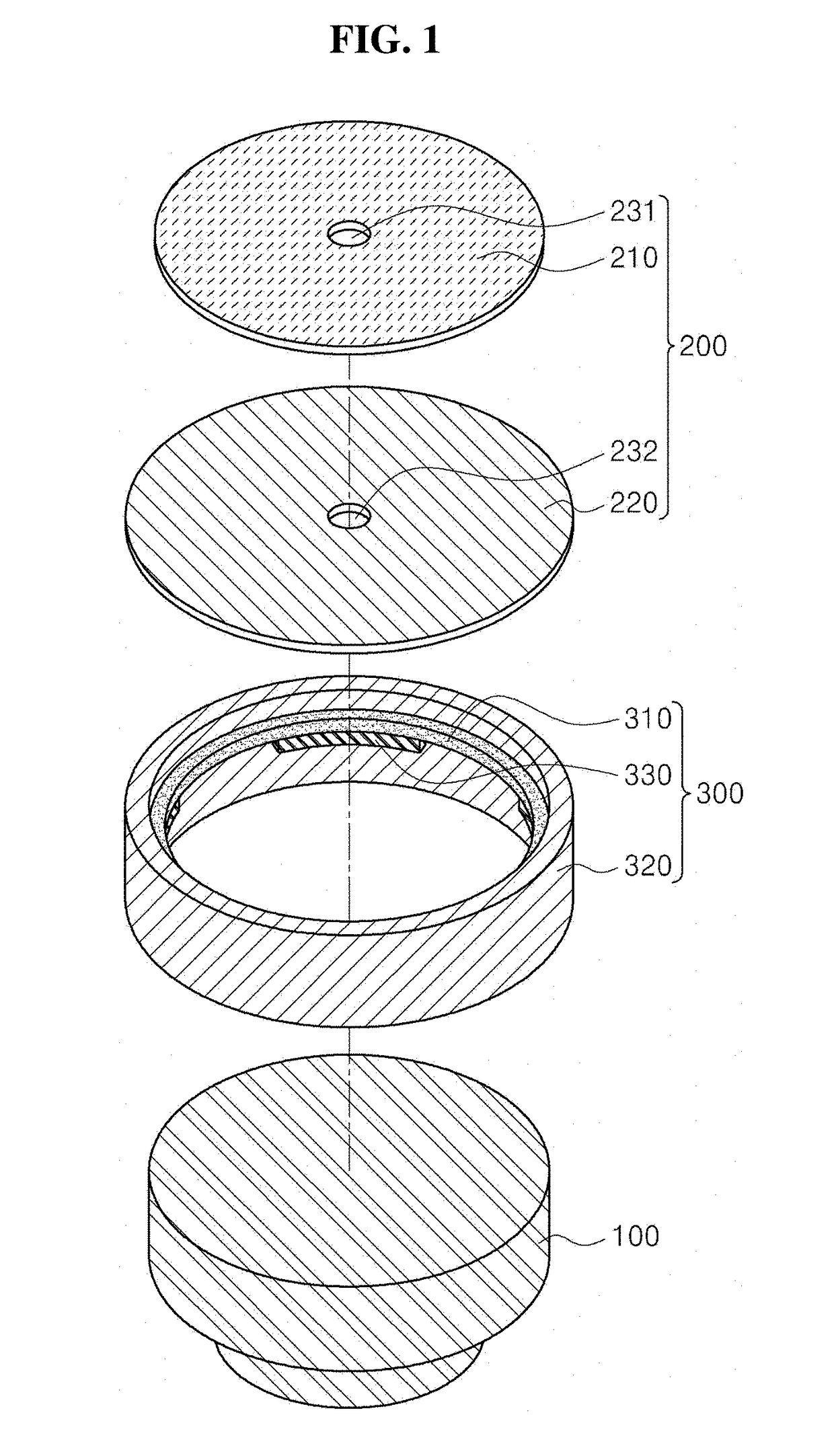
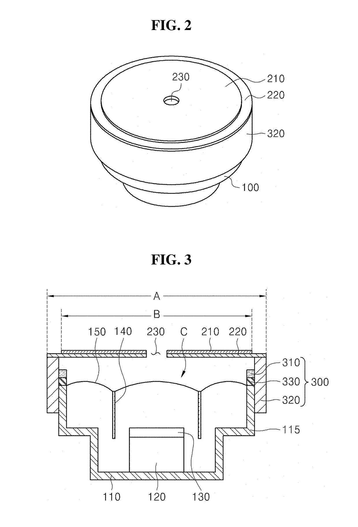
[0054]FIG. 1 is an exploded perspective view of a sound output apparatus in accordance with an exemplary embodiment, FIG. 2 is a perspective view illustrating a coupled state, and FIG. 3 is a cross-sectional view of the coupled state. Also, FIG. 4 is a perspective view of a modified example of a first sound output unit of the sound output apparatus in accordance with the exemplary embodiment

[0055]Referring to FIGS. 1 to 4, the sound output apparatus in accordance with the exemplary embodiment may include a first sound output unit 100, a second sound unit...


PUM


Abstract

The present disclosure provides a sound output apparatus including a first sound output unit, a second sound output unit spaced a predetermined distance from the first sound output unit, at least one opening defined in the second sound output unit, and a housing for accommodating at least one of the first and second sound output units. Here, the housing has an external diameter that is 100% to 130% of a diameter of the second sound output unit.

Description

1. TECHNICAL FIELD[0001]The present disclosure relates to a sound output apparatus, and more particularly, to a sound output apparatus capable of improving output characteristics of an audio frequency band including a low-pitched sound band and a high-pitched sound band.2. DESCRIPTION OF RELATED ART[0002]In general, a piezoelectric element represents an element having characteristics mutually converting electrical energy and mechanical energy to each other. That is, the piezoelectric element generates a voltage when a pressure is applied (piezoelectric effect) and generates an increase or decrease in volume or length due to a pressure variation therein when a voltage is applied (inverse piezoelectric effect). The piezoelectric element includes a piezoelectric layer and an electrode disposed thereon and has a pressure varied in accordance with a voltage applied to the piezoelectric layer through the electrode.[0003]The piezoelectric element may be used to manufacture various componen...

Claims


Application Information

Patent Timeline
IPC IPC(8): H04R1/28H04R17/00H04R23/02H04R9/02H04R1/10
CPCH04R1/28H04R17/00H04R23/02H04R9/02H04R1/1058H04R1/24H04R9/06H04R17/005H04R2201/029H04R1/2826
Inventor PARK, SUNG CHOLKIM, YOUNG SULPARK, SANG HUNJEONG, IN SEOB
Owner MODA INNOCHIPS CO LTD
Why Eureka
Try Eureka