A knitted upper for a shoe with a molded sole and a shoe

a technology of molded soles and knitted uppers, which is applied in the field of uppers for shoes with molded soles and shoes, can solve the problems of difficult to obtain the same material strength and shape as can be obtained from other materials, and achieve the effect of high stitch density

Active Publication Date: 2018-11-15
ECCO SKO
View PDF10 Cites 15 Cited by
  • Summary
  • Abstract
  • Description
  • Claims
  • Application Information

AI Technical Summary

Benefits of technology

[0011]The disclosure provides an upper for a shoe, wherein said shoe comprises said upper and a sole connected to the lower edge of said upper via injection molding, said upper comprising knitted areas with a low stitch density providing ventilation through the upper, characterized in that, said lower edge is knitted with a high stitch density, thereby limiting the flow of molding material through the edge of the knitted upper.
[0012]Thereby, a good and stable contact can be obtained when molding a sole to the upper and it is not necessary to use a strengthening rim or reinforcement elements to secure the connection. The high stitch density should be sufficiently high to at least minimize the amount of sole material that can pass through the edge during molding. Of cause, this also depends on the texture of the material used for molding the sole, where a thin texture can pass through higher stitch densities than a thick texture.

Problems solved by technology

It is also known to make knitted uppers and a problem with such knitted uppers is that it can be difficult to obtain the same material strength and shape as can be obtained from other materials.
A further problem is that when making shoes where the soles are to be molded onto the upper, it can be difficult to obtain a strong connection between the knitted upper and the molded sole.
Other problems when combining molded soles with a knitted upper may relate to:Obtaining a stable and strong connection between the sole and the upper,Ensuring that the upper can withstand the forces used when closing the lacing system,Obtaining different properties of the material in different areas of the upper.

Method used


Image

  • A knitted upper for a shoe with a molded sole and a shoe
  • A knitted upper for a shoe with a molded sole and a shoe
  • A knitted upper for a shoe with a molded sole and a shoe

Examples


Embodiment Construction

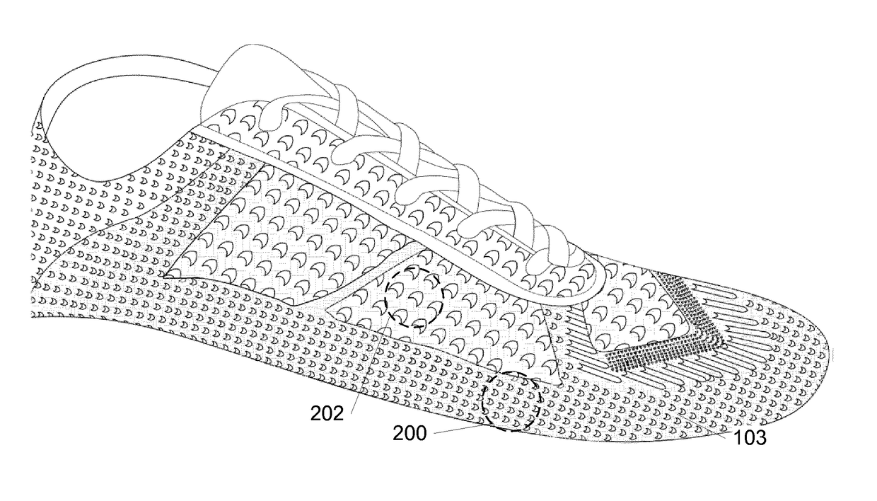
[0050]When knitting eg using knitting machines, different knitting technics imply different knitting structures and in these structures stitch densities can vary. A high density indicates a high number of stitches pr. square centimeter (high total number of needle loops in a square area) and a low density indicates a low number of stitches pr. square centimeter (low total number of needle loops in a square area). Knitted parts having a high stitch density have a more closed structure, whereas the low density knitting provides an open structure. Throughout this document reference is made to high and low stitch densities, where the high density has / may have a stitch density above 8 stitches pr. inch and more specifically between 10-12 stitches pr. Inch.

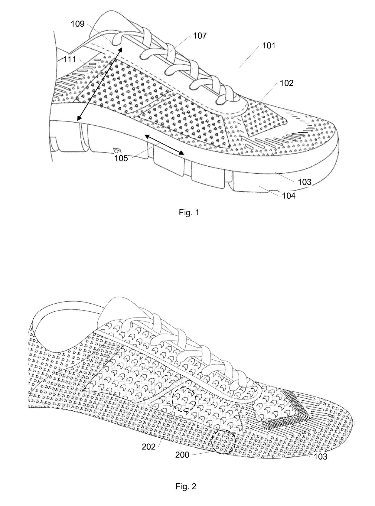
[0051]In FIG. 1, a prior art shoe 101 is illustrated and the different zones are marked and named according to the following:[0052]Upper 102 and sole 104,[0053]Lower edge 103 of upper connected to sole,[0054]Sole line area 105 being the...


PUM

PropertyMeasurementUnit
melting temperatureaaaaaaaaaa
stitch densityaaaaaaaaaa
moldingaaaaaaaaaa

Abstract

An upper for a shoe, where said shoe comprises said upper and a sole connected to the lower edge of the upper via injection molding, the upper including knitted areas with a low stitch density providing ventilation through the upper, where the lower edge is knitted with a high stitch density, thereby limiting the flow of molding material through the edge of the knitted upper.

Description

TECHNICAL FIELD[0001]The current invention relates to an upper for a shoe with a molded sole and a shoe comprising a knitted upper with a molded sole.BACKGROUND[0002]When making shoes, two main elements influence the final appearance of the shoe and these elements are comfort and design.[0003]A shoe comprises the following elements:[0004]Sole—All shoes have a sole, which is the bottom of a shoe that is in contact with the ground and may consist of an insole, midsole, and an outsole. The insole is the interior bottom of a shoe that sits directly beneath the foot under the footbed (also known as sock liner). The outsole is the layer in direct contact with the ground. Dress shoes often have leather or resin rubber outsoles; casual or work-oriented shoes have outsoles made of natural rubber or a synthetic material like polyurethane. The outsole may comprise a single piece, or may be an assembly of separate pieces, often of different materials. On some shoes, the heel of the sole has a r...

Claims


Application Information

Patent Timeline
Patent Type & Authority Applications(United States)
IPC IPC(8): A43B23/02D04B1/10A43B13/14A43B13/04B29D35/00B29D35/06
CPCA43B23/025D04B1/106A43B23/0215A43B23/0265A43B13/14A43B13/04B29D35/0009B29D35/064D10B2501/043D10B2331/04A43C5/00A43B23/0245B29D35/061B29D35/068
Inventor T STENSEN, NIKIBOVE, SAVINO PAULO
Owner ECCO SKO
Why Eureka
Try Eureka