
Positive interlock network (PIN) vise and mold

Active Publication Date: 2018-11-15
MILLERSVILLE UNIVERSITY OF PENNSYLVANIA
View PDF9 Cites 0 Cited by
  • Summary
  • Abstract
  • Description
  • Claims
  • Application Information

AI Technical Summary

Benefits of technology

The patent describes a way to hold an object securely using a pin array. The technical effect is the creation of a secure network through which the objects can be connected and cooperate with each other.

Problems solved by technology

These irregularly shaped parts may lack symmetry or flat surfaces or must be positioned in an orientation that complicates typical workpiece holding methods.
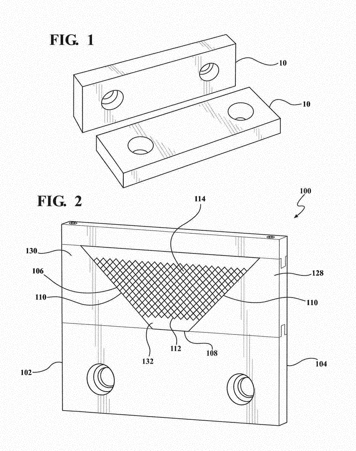
The disadvantage of standard vise jaws, shown in FIG. 1, is that flat surfaces do not provide good support for round or abnormally shaped parts.
Although round parts can be accommodated through the use of accessories such as V-blocks, this does not address irregular geometries.

Method used


Image

  • Positive interlock network (PIN) vise and mold
  • Positive interlock network (PIN) vise and mold
  • Positive interlock network (PIN) vise and mold

Examples


Embodiment Construction

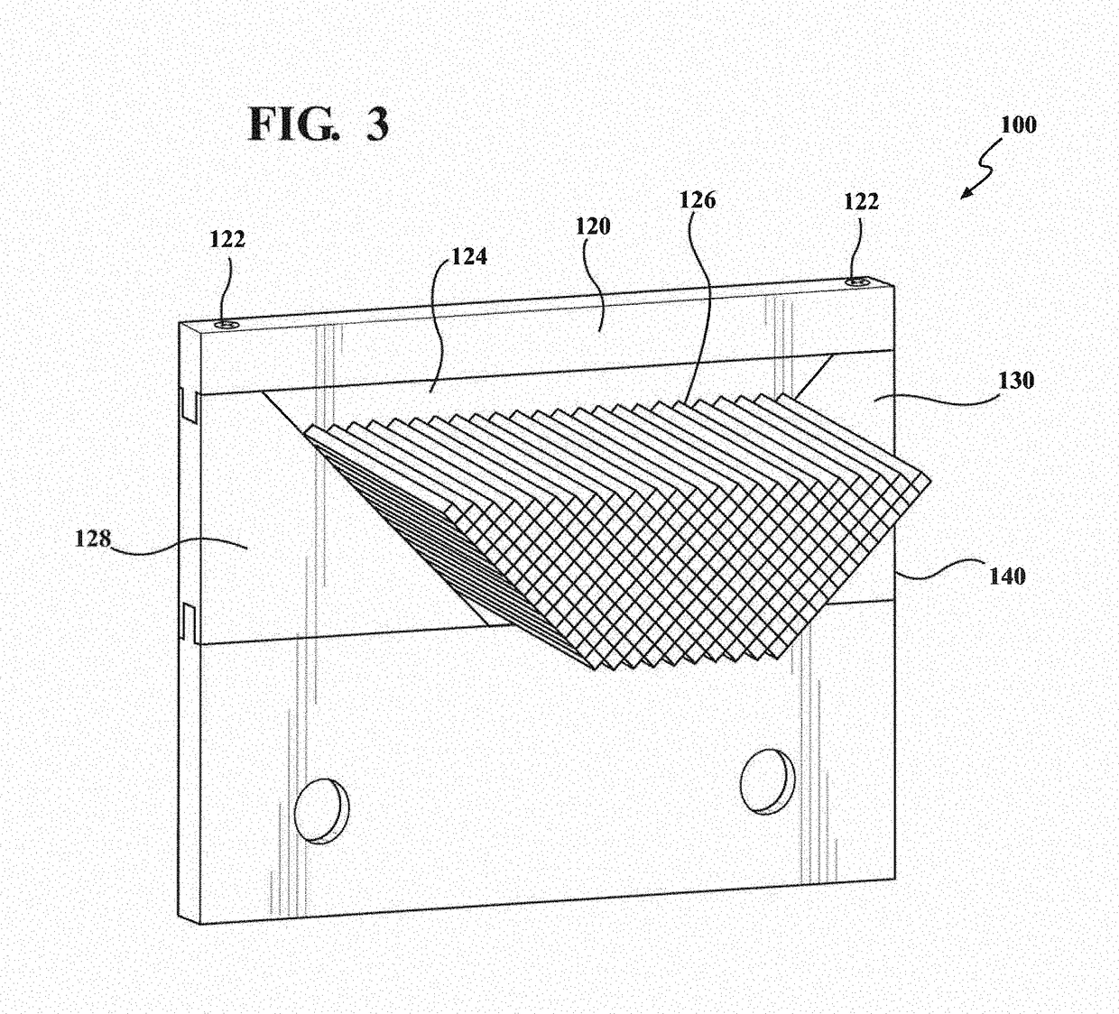
[0041]The concept of the design of a PIN vise in accordance with an embodiment of the present invention is shown in FIGS. 2-5.

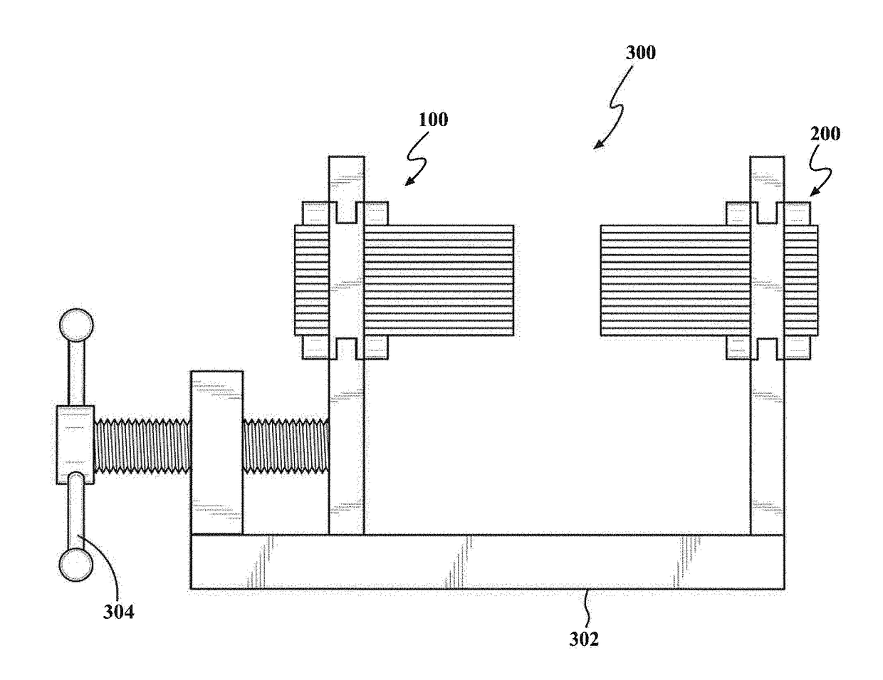
[0042]FIG. 5 shows an example of a pin vise 300 according to an embodiment of the present invention. The pin vise 300 may be mounted on a base 302. The vise includes two jaws 100, 200. Only one of the jaws can be moved relative to the base so that the distance between the jaws 100, 200 can be adjusted. Alternatively, both jaws may be movable. When an object is placed between two jaws, the jaw 100 is moved to approach the jaw 200, the pins will come in contact with the object and form a shape of the object. The object will be eventually clamped by the pins.

[0043]The two jaws may be same. The jaws may also be different. For example, a vise may include a jaw with pins and a flat jaw. A vise may include two jaws with pins but the pins on one jaw may be different from the pins on the other jaw. FIGS. 2-4 show different views of one of the jaws 100 of the pin vise ...


PUM


Abstract

A vise includes a base and two opposed jaws. At least one of the jaws is movable with respect to the other so that an object can be gripped therebetween. At least one of the two opposed jaws includes a frame and an array of polygon-shaped pins stacked parallel to one another. The frame has a bottom side and two opposed sides tapering towards the bottom side. The pins are disposed on the bottom side. Each pin has a cross-sectional shape such that when stacked together, the pins fit flush with one another and an area defined by the frame is tiled by the pins without any substantial gaps therebetween. The pins are oriented such that the tapering opposed sides direct force vectors to increase a pin-to-pin clamping force and the frame selectively clamps down on the pins such that the pins are held in place.

Description

REFERENCE TO RELATED APPLICATION[0001]This application claims priority from U.S. Provisional Patent Application Ser. No. 62 / 505,464, filed May 12, 2017, the entire content of which is incorporated herein by reference.FIELD OF THE INVENTION[0002]The present invention relates to a device and method for holding a workpiece and, in particular, relates to an adjustable vise.BACKGROUND OF THE INVENTION[0003]Irregularly shaped parts are frequently encountered in cast and forged components which require finishing operations. These irregularly shaped parts present significant challenges when being held with a typical vise, as shown in FIG. 1. These irregularly shaped parts may lack symmetry or flat surfaces or must be positioned in an orientation that complicates typical workpiece holding methods. The disadvantage of standard vise jaws, shown in FIG. 1, is that flat surfaces do not provide good support for round or abnormally shaped parts. Although round parts can be accommodated through the...

Claims


Application Information

Patent Timeline
IPC IPC(8): B25B1/10B25B1/24
CPCB25B1/103B25B1/2452B25B1/2421B25B1/2468
Inventor ATWATER, MARK ANDREWHA, ANDREW
Owner MILLERSVILLE UNIVERSITY OF PENNSYLVANIA
Learn More