Supercharge Your Innovation With Domain-Expert AI Agents!

Volute casing for a centrifugal pump and centrifugal pump

a centrifugal pump and valve casing technology, which is applied in the direction of non-positive displacement pumps, engine fuctions, liquid fuel engines, etc., can solve the problems of strong pressure blowing, gas bubble formation, and occurrence of cavitation, so as to reduce the risk of cavitation, in particular in the operating range of the part-load pump, the effect of reducing the risk

Active Publication Date: 2018-11-15
SULZER MANAGEMENT AG
View PDF2 Cites 1 Cited by
  • Summary
  • Abstract
  • Description
  • Claims
  • Application Information

AI Technical Summary

Benefits of technology

The invention is a new design for the volute casing of a centrifugal pump that reduces the risk of cavitation, especially when the pump is operating off its best efficiency point or design flow rate. The design includes a specific design of the inner surface of the cutwater area, which reduces local velocity peaks and eliminates the risk of cavitation. Additionally, the design also recommends an inclination angle of at least 110° between the profile chord and a straight line connecting the cutwater minimum point with the central axis. This further improves the efficiency of the pump.

Problems solved by technology

A known problem of volute casings is the occurrence of cavitation, in particular at the cutwater where the liquid has a very high flow velocity.
The high flow velocity may decrease the local pressure below the vapor pressure of the liquid which results in the formation of gas bubbles.
The gas bubbles will implode thereby generating strong pressure blows.
This phenomenon is also as known as casing cavitation and has several negative impacts, for example increased vibrations and noise of the pump, a reduced differential head, instabilities in the head performance curve and severe erosion at the casing reducing the lifetime of the casing.
The risk of cavitation is particularly high when the pump is operated off the best efficiency point, for example at part-load when the pump generates a flow rate which is remarkably below the flow rate the pump is designed for, or at over-load when the pump generates a flow rate that is considerably higher than the flow rate the pump is designed for.
One distinct peculiarity of such operations away from the best efficiency point is the mismatch between the flow angle and cutwater angle, which results in localized flow velocity peaks with the magnitude of the velocity peak usually increasing with increasing distance from the best efficiency point or from the design flow rate, respectively.
However, increasing the suction pressure is not possible in many applications because in the majority of existing pump installations the suction pressure is a boundary condition that cannot be modified.
But even if the suction pressure might be increased this requires more energy, additional equipment, efforts and costs.

Method used


Image

  • Volute casing for a centrifugal pump and centrifugal pump
  • Volute casing for a centrifugal pump and centrifugal pump
  • Volute casing for a centrifugal pump and centrifugal pump

Examples


Embodiment Construction

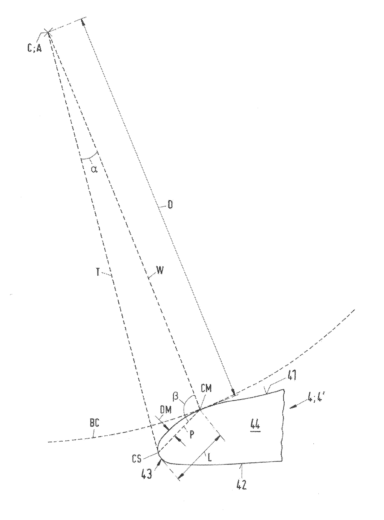
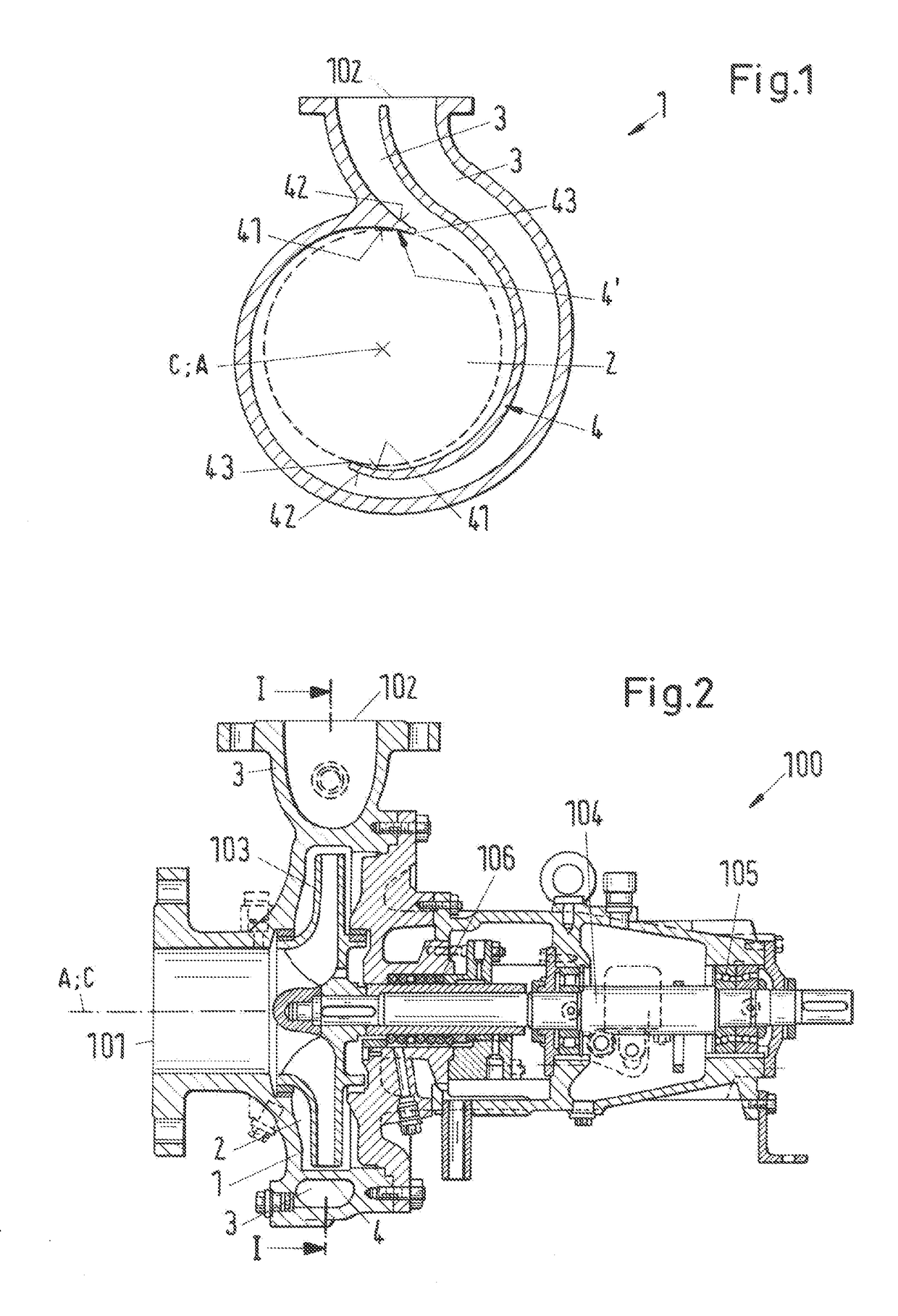
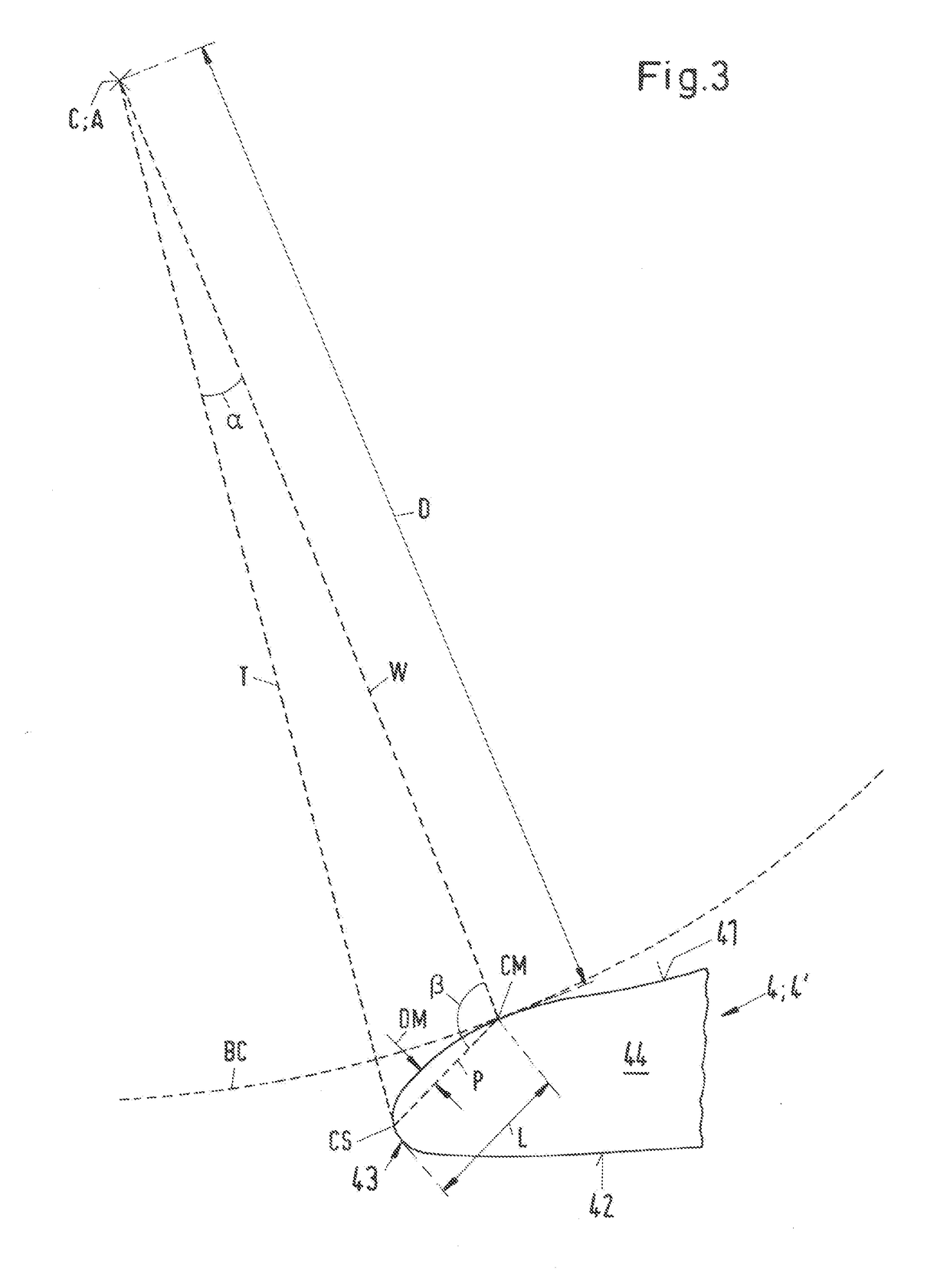
[0030]FIG. 1 is a cross-sectional schematic view of an embodiment of a volute casing according to the invention, which is designated in its entity with reference numeral 1. FIG. 2 is a cross-sectional view of an embodiment of a centrifugal pump according to the invention, which is designated in its entity with reference numeral 100, and which comprises the volute casing 1 shown in FIG. 1. The centrifugal pump 100 comprises an inlet 101 through which a fluid, in particular a liquid, for example water, can enter the pump 100 as well as an outlet 102 for discharging the fluid. The pump 100 further comprises at least one impeller 103 for acting on the fluid. The impeller 103 is arranged within a volute chamber 2 of the volute casing 1. During operation, the impeller 103 is rotating about a rotational axis extending in an axial direction A. The volute casing1 comprises a central axis C coinciding with the rotational axis of the pump 100. Thus, the axial direction A is defined by the cent...


PUM


Abstract

A volute casing includes a chamber, an outlet passage, and a cutwater to direct fluid to the outlet passage. The cutwater includes an inner surface, an outer surface and a leading edge joining the inner and outer surfaces and has a cross-sectional contour in a midplane perpendicular to the axial direction. The cross-sectional contour includes a starting point at the leading edge, and a minimum point on the inner surface, the starting point defined by a tangent to the leading edge, the tangent intersecting the central axis, and the minimum point defined by a location, at which the inner surface has a minimum distance from the central axis. A straight profile chord located in the cross-sectional contour, and extending from the cutwater starting point to the cutwater minimum point, has a maximum orthogonal distance from the inner surface being at most 15% of the length of the profile chord.

Description

CROSS-REFERENCE TO RELATED APPLICATION[0001]This application claims priority to European Application No. 17170250.9, filed May 9, 2017, the contents of which are hereby incorporated herein by reference.BACKGROUNDField of the Invention[0002]The invention relates to a volute casing for a centrifugal pump and to a centrifugal pump.Background of the Invention[0003]Centrifugal pumps with volute casings are used for many different applications. The characteristic feature of a volute casing is a volute chamber for receiving the impeller of the pump, wherein the distance between the inner wall delimiting the volute chamber and the central axis of the volute casing (the axis about which the impeller rotates during operation) increases when viewed in the flow direction towards the outlet passage of the volute casing. Centrifugal pumps with a volute casing may be designed as single stage or multistage pumps, with a single suction design or a double suction design on the first stage. The fluid,...

Claims


Application Information

Patent Timeline
Patent Type & Authority Applications(United States)
IPC IPC(8): F04D29/42F04D29/44F04D29/66
CPCF04D29/4233F04D29/445F04D29/428F04D29/663F05D2260/96F05D2240/121F04D29/426F04D29/669F04D1/00
Inventor MAROCCIA, BRUNO
Owner SULZER MANAGEMENT AG
Features
  • R&D
  • Intellectual Property
  • Life Sciences
  • Materials
  • Tech Scout
  • Unparalleled Data Quality
  • Higher Quality Content
  • 60% Fewer Hallucinations
Learn More