Pulsed radar level gauge system and method for reduced relative bandwidth

a technology of radar level gauge and pulsed radar, which is applied in the direction of engine lubrication, liquid/fluent solid measurement, reradiation, etc., can solve the problem of limited design options for such a wideband coupling

Inactive Publication Date: 2018-11-15
ROSEMOUNT TANK RADAR
View PDF3 Cites 7 Cited by
  • Summary
  • Abstract
  • Description
  • Claims
  • Application Information

AI Technical Summary

Benefits of technology

[0014]In view of the above, a general object of the present invention is to provide an improved radar level gauge sys

Problems solved by technology

However, design options for such a wideband coupling are limited, so that vario

Method used


Image

  • Pulsed radar level gauge system and method for reduced relative bandwidth
  • Pulsed radar level gauge system and method for reduced relative bandwidth
  • Pulsed radar level gauge system and method for reduced relative bandwidth

Examples


Embodiment Construction

[0065]In the present detailed description, various embodiments of the present invention are mainly discussed with reference to a pulsed radar level gauge system with a non-conductive coupling between transceiver and probe.

[0066]It should be noted that this by no means limits the scope of the present invention, which also covers a pulsed radar level gauge system with other couplings between transceiver and probe, such as a conventional conductive coupling between transceiver and probe.

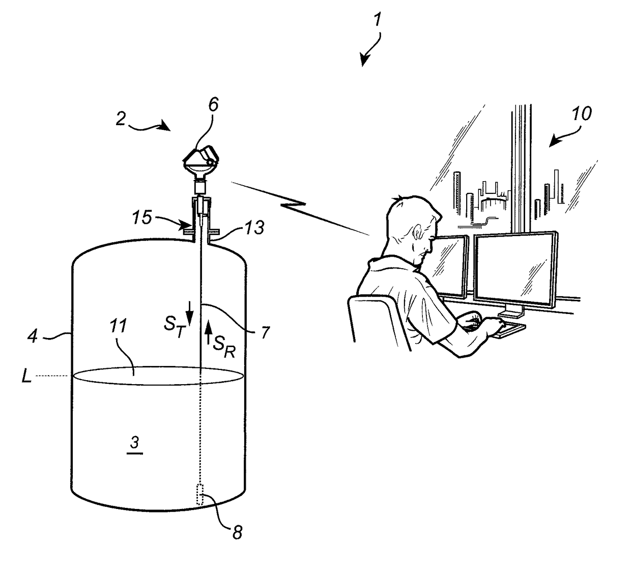
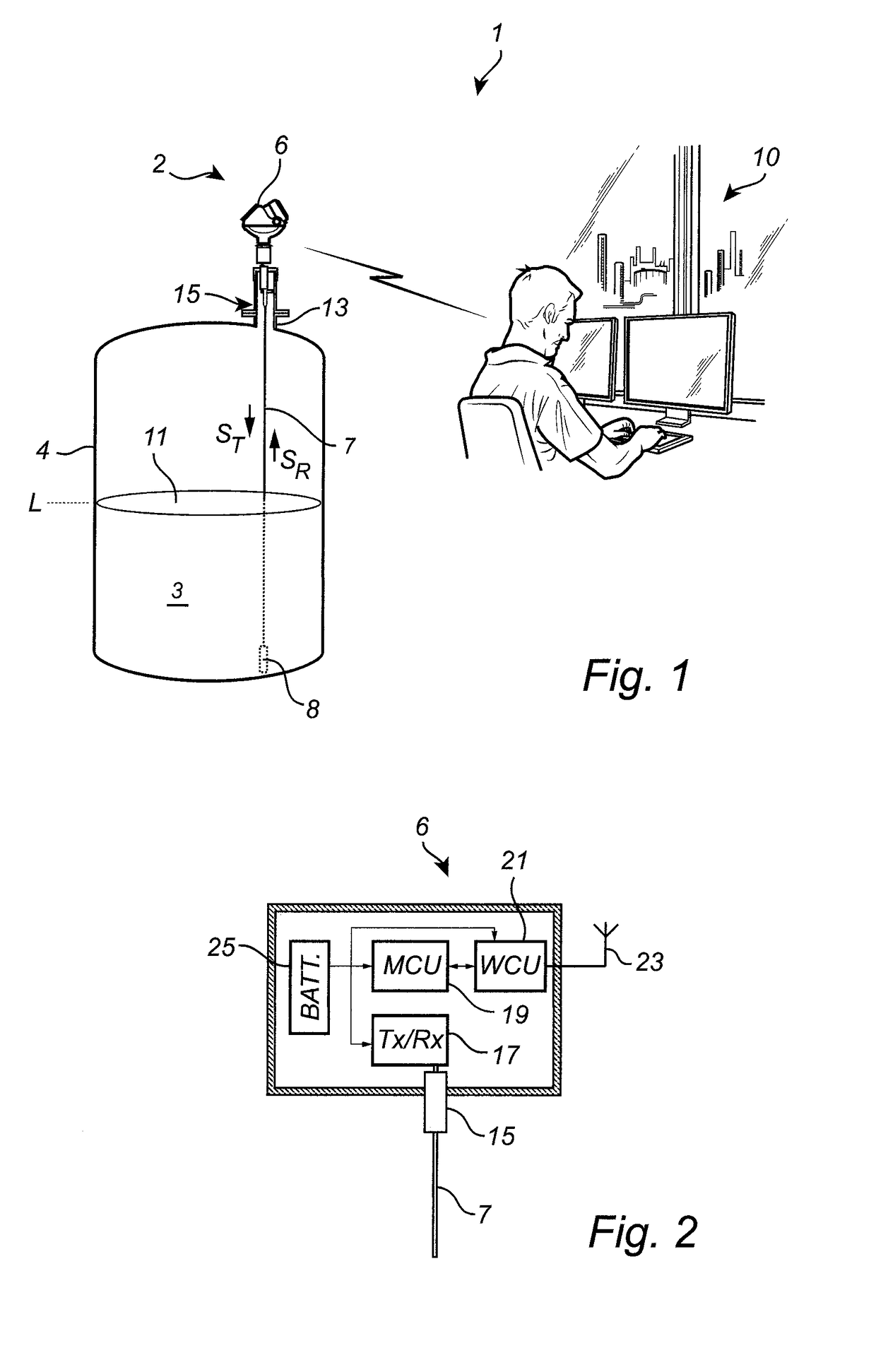
[0067]FIG. 1 schematically shows a level measuring system 1 comprising a radar level gauge system 2 according to an example embodiment of the present invention, and a host system 10 illustrated as a control room.

[0068]The radar level gauge system 2 of GWR (Guided Wave Radar) type is installed at a tank 4 having a tubular mounting structure 13 (often referred to as a “nozzle”) extending substantially vertically from the roof of the tank 4.

[0069]The radar level gauge system 2 is installed to measure the f...


PUM


Abstract

A radar level gauge system comprising: pulse generating circuitry for generating an electromagnetic transmit signal in the form of a first pulse train formed by a time-sequence of substantially identical transmit pulses, each exhibiting a full period waveform; and an electromagnetic reference signal in the form of a second pulse train formed by a time-sequence of substantially identical reference pulses, each exhibiting a half period waveform; a propagation device arranged to propagate the transmit signal towards a product in a tank, and to return a surface reflection signal resulting from reflection of the transmit signal at a surface of the product; measurement circuitry for forming a measurement signal based on a time-correlation between the surface reflection signal and the reference signal; and processing circuitry connected to the measurement circuitry for determining the filling level based on the measurement signal.

Description

TECHNICAL FIELD OF THE INVENTION[0001]The present invention relates to a pulsed radar level gauge system, and to a method of determining a filling level of a product in a tank.TECHNICAL BACKGROUND[0002]Radar level gauge (RLG) systems are in wide use for determining filling levels in tanks. Radar level gauging is generally performed either by means of non-contact measurement, whereby electromagnetic signals are radiated towards the product in the tank, or by means of contact measurement, often referred to as guided wave radar (GWR), whereby electromagnetic signals are guided towards and into the product by a probe acting as a waveguide. The probe is generally arranged to extend vertically from the top towards the bottom of the tank.[0003]An electromagnetic transmit signal is generated by a transceiver and propagated towards the surface of the product in the tank, and an electromagnetic reflection signal resulting from reflection of the transmit signal at the surface is received by th...

Claims


Application Information

Patent Timeline
IPC IPC(8): G01F23/284
CPCG01F23/284G01S7/282G01S13/103G01S13/30
Inventor EDVARDSSON, OLOV
Owner ROSEMOUNT TANK RADAR
Why Eureka
Try Eureka