Method and system for emulating modular agnostic control of commercial unmanned aerial vehicles (UAVS)

Active Publication Date: 2018-11-15
PERCEPTO ROBOTICS LTD
View PDF0 Cites 2 Cited by
  • Summary
  • Abstract
  • Description
  • Claims
  • Application Information

AI Technical Summary

Benefits of technology

The present invention describes a system for controlling drones using sensors, a processor, and a remote controller. The system detects and provides flight control parameters within a predetermined area of the drone's operation and processes them using a companion flight control processor. The system also includes a central field-programmable gate array (FPGA) that is integrated in the drone and can communicate with the primary flight control processor and the companion flight control processor. This FPGA can act as a real-time controller between the two processors and allow for agnostic control of the drone. The technical effects of this system include improved efficiency and safety during drone operations.

Problems solved by technology

First, the use of functional / operational technical descriptions allows near- infinitely complex machines and machine operations arising from interchained hardware elements to be described in a manner that the human mind can process (e.g., by mimicking natural language and logical narrative flow).
After many years of growth and innovation mainly in military segment, the global UAV industry is now going through a challenging period, with possible increasing of market dynamics towards wider use of UAVs for commercial and civil purposes.
None of the current technologies and prior art, taken alone or in combination, does not address nor provide a truly integrated solution for developing capabilities for emulating an agnostic control of position, course or altitude of the remotely controlled unmanned aerial vehicles via a central field-programmable gate array (FPGA), that can be installed and configured on any of commercial drones, unifying the vast network of currently deployed commercial unmanned aerial vehicles.
Therefore, there is a long felt and unmet need for a system and method that overcomes the problems associated with the prior art.

Method used


Image

  • Method and system for emulating modular agnostic control of commercial unmanned aerial vehicles (UAVS)
  • Method and system for emulating modular agnostic control of commercial unmanned aerial vehicles (UAVS)
  • Method and system for emulating modular agnostic control of commercial unmanned aerial vehicles (UAVS)

Examples


Embodiment Construction

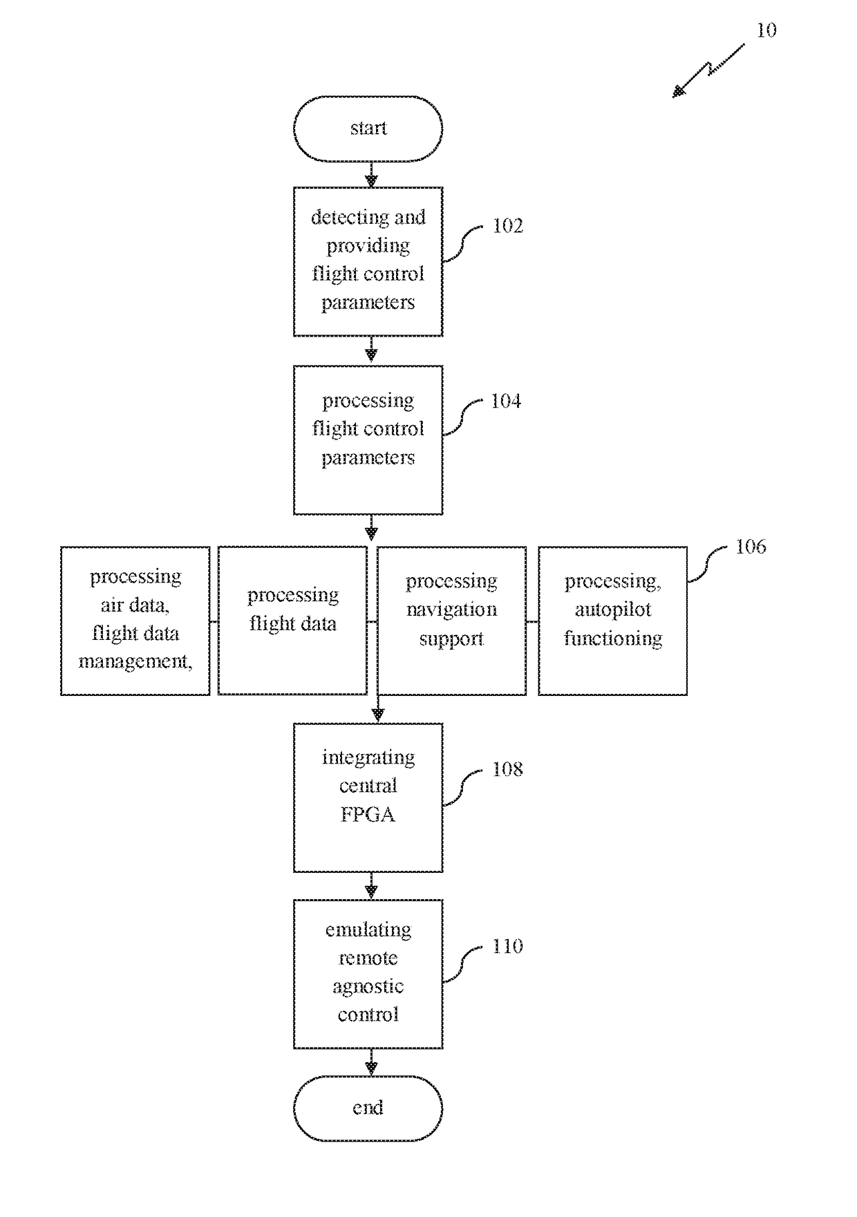
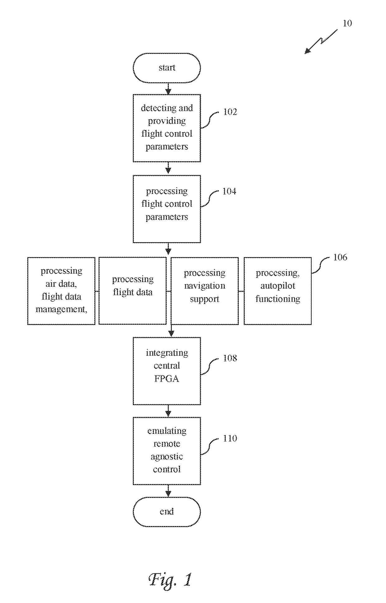
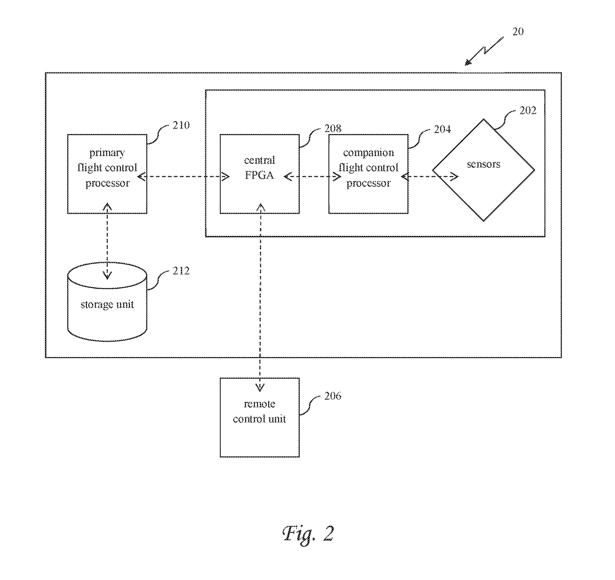
[0024]In the following detailed description of the preferred embodiments, reference is made to the accompanying drawings that form a part hereof, and in which are shown by way of illustration specific embodiments in which the invention may be practiced. It is understood that other embodiments may be utilized and structural changes may be made without departing from the scope of the present invention. The present invention may be practiced according to the claims without some or all of these specific details. For the purpose of clarity, technical material that is known in the technical fields related to the invention has not been described in detail so that the present invention is not unnecessarily obscured.

[0025]Reference throughout this specification to “one embodiment” or “an embodiment” means that a particular feature, structure, or characteristic described in connection with the embodiment is included in at least one embodiment of the present invention. Thus, the appearances of...


PUM


Abstract

A method for emulating control signals for controlling an unmanned aerial vehicle (UAV). The method comprises using an integrated circuit installed on the UAV and communicatively coupled to a flight control processor and a companion processor for receiving flight control parameters from the companion processor, the flight control parameters are based data from a plurality of sensors communicatively coupled to the companion processor and mounted on the UAV, wirelessly receiving remote control signals from a remote control unit, modulating the flight control parameters to create emulated signals emulating a signals generated by a remote control designated to wirelessly control the UAV, the emulated signals encode instructions to maneuver the UAV, and switching between the remote control signals and the emulated signals during a flight time of the UAV.

Description

RELATED APPLICATIONS[0001]This application is a Continuation-in-Part (CIP) of PCT Patent Application No. PCT / IL2017 / 050056 filed on Jan. 17, 2017, which claims the benefit of priority under 35 USC 119(e) of U.S. Provisional Patent Application No. 62 / 280,131 filed on Jan. 19, 2016, the contents of which are incorporated herein by reference in their entirety.FIELD AND BACKGROUND OF THE INVENTION[0002]The present invention generally relates to emulation of agnostic control of position, course or altitude of land, water, air, or space vehicles, and particularly to the remotely controlled unmanned aerial vehicles and their coordination via a central field-programmable gate array (FPGA).[0003]The claims, description, and drawings of this application may describe one or more of the instant technologies in operational / functional language, for example as a set of operations to be performed by a computer. Such operational / functional description in most instances would be understood by one ski...

Claims


Application Information

Patent Timeline
IPC IPC(8): G05D1/00G05D1/08B64C39/02
CPCG05D1/0077G05D1/0022G05D1/0808G05D1/0094B64C39/024B64C2201/146B64C2201/127H04L25/4902G05D1/00G05D1/0011G05B2219/21109G05B13/042G05D1/0088B64U2101/30B64U2201/20
Inventor ABUHASIRA, DORBLONDER, SAJIRAZ, RAVIV
Owner PERCEPTO ROBOTICS LTD
Why Eureka
Try Eureka