
Eureka
For R&D, Eureka makes reading and utilizing patents & technical documents easy.
Eureka AIR
Designed for self-driven R&D workflows. Generate viable solutions, solve complex R&D challenges, empower your innovation with AI.

Eureka Materials
Designed for material experts only. Revolutionize your material R&D, from search, analyze, to developing new materials.

TechResearch
Generate reliable direction feasibility study reports for your R&D in just a few steps.

TechSeek
Discover and master advanced knowledge NOW. Basics, ideas, possibilities, all at once.

TechMind
As an expert in R&D Theories, TechMind can generates customized viable solutions instantly.

TechRisk
Analyze your overall solution with one click, know your potential R&D risks in advance.

TechMonitor
Get weekly tech updates, stay abreast of the latest tech innovations and key insights.
Rotating electrical machine
- Summary
- Abstract
- Description
- Claims
- Application Information
AI Technical Summary
Benefits of technology
Problems solved by technology
Method used
Image

Examples
embodiments
[0029]Each of the embodiments refers to an ac generator (i.e., an alternator) for automotive vehicles as a typical example of a rotating electrical machine. The following discussion will first refer to an outline of a basic structure of the automotive ac generator, to features and basic operations in each of the embodiments and then to beneficial advantages offered by each of the features.
[0030]In the drawings, like reference numbers or symbols will refer to like parts throughout the several views. Explanation overlapping between the embodiments will be omitted.
[0031]Matters common to the embodiments will be described below using FIGS. 1 to 4.
Basic Structure of AC Generator G
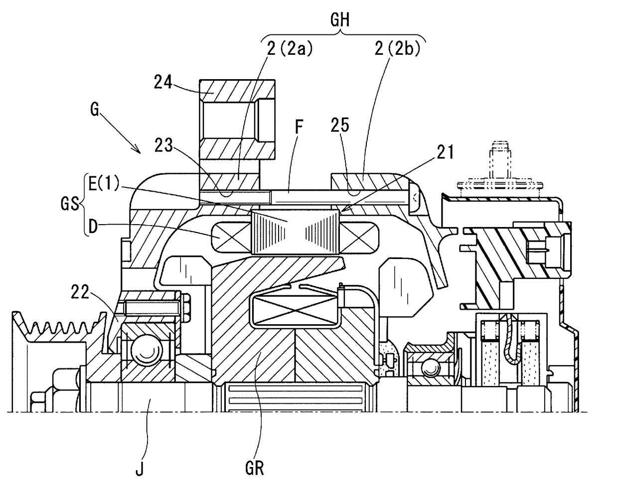
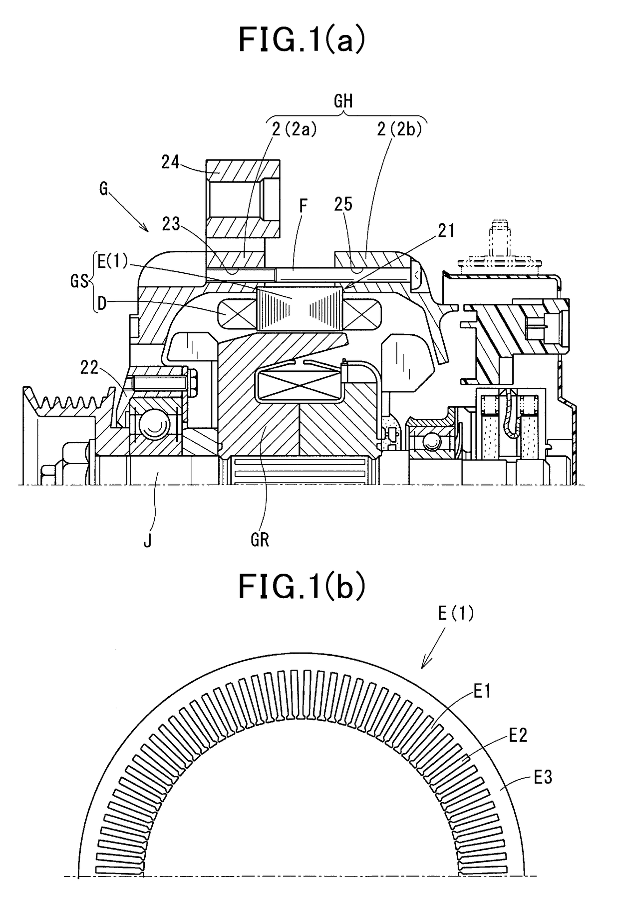
[0032]The ac generator G is, as illustrated in FIG. 1(a), secured to the rotating shaft J driven by an engine and equipped with the rotor GR acting as a field, the stator GS which is disposed around an outer periphery of the rotor GR as an armature, and the generator housing GH in which the stator GS and the rot...
first embodiment
Feature of Generator Housing GH
[0043]The housings 2 of the generator housing GH in this embodiment, as described already, basically have the spigot and socket joint mechanisms 21 in the form of a shoulder-shaped recess which has the feature. The specific structure of the spigot and socket joint mechanism 21 will be described in detail with reference to FIG. 5.
[0044]The spigot and socket joint mechanism 21 has the annular holding surface 26 as an orthogonal shoulder surface which nips the end surfaces of the stator core E in the axial direction and the cylindrical guide surface 27 which guides an outer peripheral surface of the stator core E. The surfaces 26 and 27 are arranged perpendicular to each other in an L-shape through the clearance groove 28.
[0045]The spigot and socket joint mechanism 21 adopts a novel structure to the annular holding surface 26 which holds the stator core E in the axial direction. Specifically, the holding surface 26 has two annular surfaces: the first annu...
second embodiment
[0057]Differences between the second embodiment and the first embodiment will be described below with reference to FIG. 6.
[0058]The feature of the stator mounting mechanism in the second embodiment is that a stepped configuration of the annular holding surface 26 is larger in size than that in the first embodiment.
[0059]The annular holding surface 26, as illustrated in FIG. 6, includes two concentric parallel surfaces: the first annular surface 26a and the second annular surface 26b which are different in diameter from each other. The large-diameter second annular surface 26b has a special stepped relation with the small-diameter first annular surface 26a in which the second annular surface 26b protrudes outside the first annular surface 26a in the axial direction by a height γ which is greater than the height β in the first embodiment. The stepped relation means a difference in level between the first contacting portion and the second contacting portion in the axial direction. The ...
PUM
 Abstract
Description
Claims
Application Information
 - R&D Engineer
- R&D Manager
- IP Professional
- Industry Leading Data Capabilities
- Powerful AI technology
- Patent DNA Extraction
Browse by: Latest US Patents, China's latest patents, Technical Efficacy Thesaurus, Application Domain, Technology Topic, Popular Technical Reports.
© 2024 PatSnap. All rights reserved.Legal|Privacy policy|Modern Slavery Act Transparency Statement|Sitemap|About US| Contact US: help@patsnap.com