Compact Sharpening Filter For Orthovoltage X-Rays

a technology of orthovoltage x-rays and sharpening filters, which is applied in the field of orthovoltage x-ray machines for radiation therapy, to achieve the effects of convenient installation and replacement, improved operation, and versatility

Active Publication Date: 2018-11-22
WISCONSIN ALUMNI RES FOUND
View PDF0 Cites 0 Cited by
  • Summary
  • Abstract
  • Description
  • Claims
  • Application Information

AI Technical Summary

Benefits of technology

[0008]The present invention provides a sharpening filter for orthovoltage x-ray beams (200 kVp-500 kVp) providing improved operation, versatility, or manufacturability. The filter uses an axially compact filter plate having concentric circular attenuation regions to

Problems solved by technology

Unfortunately, the focal spot sizes for orthovoltage units are larger than t

Method used


Image

  • Compact Sharpening Filter For Orthovoltage X-Rays
  • Compact Sharpening Filter For Orthovoltage X-Rays
  • Compact Sharpening Filter For Orthovoltage X-Rays

Examples


second embodiment

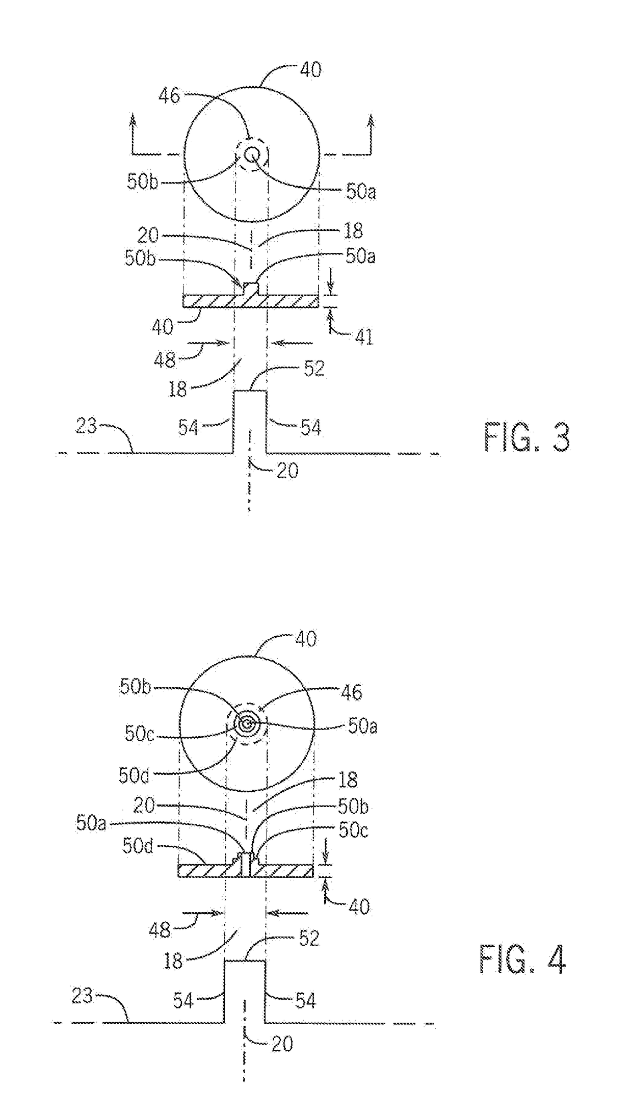
[0038]In a second embodiment shown in FIG. 4, for the x-ray source assembly 12 of FIG. 2 and for a channel diameter of six-millimeters, the single central pillar may be replaced by a single central aperture attenuation region 50a passing through the filter disk 40. Surrounding this aperture attenuation region 50a is a first ring of increased axial thickness providing attenuation region 50b and a second ring of increased axial thickness (but less axial thickness than attenuation region 50b) providing attenuation region 50c. Finally, attenuation region 50c is surrounded by a lower attenuation region 50d being essentially this nominal thickness of the filter disk 40 of approximately 0.5 millimeters. The aperture of attenuation region 50a may be approximately 1 millimeter in diameter. Attenuation region 50b may be approximately 1.5 millimeters in axial height, and attenuation region 50c may be approximately 1 millimeter in axial height, with each radial wall thickness approximately 0.5 ...

third embodiment

[0039]In a third embodiment, shown in FIG. 5 for the x-ray source assembly 12 of FIG. 2 for channel diameter of 8 millimeters, the central attenuation region 50a may be a pillar extending axially from the surface of the filter disk 40 surrounded by an annular moat forming attenuation region 50b and having the nominal axial thickness of 0.5 millimeters of the filter disk 40. This attenuation region 50b may be surrounded in turn by an attenuation region 50c of increased thickness which is then finally surrounded by yet another reduced attenuation region providing attenuation region 50d equal substantially to the thickness of the filter disk 40 of 0.5 millimeters. The central pillar of attenuation region 50a may have a diameter (measured perpendicularly to axis 20) of one millimeter and a height (measured along axis 20) of approximately 0.5 millimeters in the attenuation region 50c and may have a radial wall thickness (measured perpendicularly to axis 20) of approximately one millimete...


PUM


Abstract

A sharpening filter for orthovoltage x-ray beams employs a substantially planar filter disk supporting a set of radial symmetric features controlling attenuation of x-ray transmission in concentric circular regions providing increased sharpness of the pencil beams in a compact filter structure that may be tailored to different beam sizes and focus depths.

Description

STATEMENT REGARDING FEDERALLY SPONSORED RESEARCH OR DEVELOPMENT[0001]--CROSS REFERENCE TO RELATED APPLICATION[0002]--BACKGROUND OF THE INVENTION[0003]The present invention relates to orthovoltage x-ray machines for radiation therapy and in particular to a filter for improving the sharpness of radiation beams generated by such machines.[0004]Many stereotactic radiosurgery (SRS) and stereotactic body radiation therapy (SBRT) treatments require highly conformal dose distributions with sharp dose gradients at the target periphery. Delivering a more homogeneous dose to the target volume has been associated with reduced adverse effects and toxicities. Delivering a precise dose to the target volume also allows for the prescription to a higher isodose volume without excessive dose to nearby critical structures.[0005]One method for achieving sharp dose distributions is through modulation of the SRS beam combined with the use of low energies. Previous work with 6 megavolt SRS pencil beams has...

Claims


Application Information

Patent Timeline
IPC IPC(8): A61N5/10
CPCA61N5/1077A61N2005/1095A61N2005/1091
Inventor FAGERSTROM, JESSICABENDER, EDWARDCULBERSON, WESLEYLAWLESS, MICHAELPALMER, BENJAMIN R.M.DEWERD, LARRY
Owner WISCONSIN ALUMNI RES FOUND
Why Eureka
Try Eureka