Programming device and robot control method

Active Publication Date: 2018-11-22
FANUC CORP
View PDF0 Cites 8 Cited by
  • Summary
  • Abstract
  • Description
  • Claims
  • Application Information

AI Technical Summary

Benefits of technology

[0016]According to the present invention, it is possible to perform

Problems solved by technology

However, in the case of causing the robot to actually operate using an operating program generated by way of OPS, it is often not possible for the robot to execute the work as expected, for reasons such as dimensional error or assembl

Method used


Image

  • Programming device and robot control method
  • Programming device and robot control method
  • Programming device and robot control method

Examples


embodiment

Configuration of Embodiment

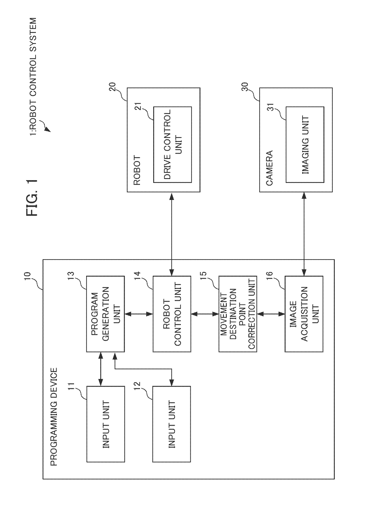
[0031]First, the overall configuration of a robot control system 1 which is the present embodiment will be explained by referencing FIG. 1. The robot control system 1 includes a programming device 10, a robot 20 and a camera 30, as shown in FIG. 1.

[0032]The programming device 10 and the robot 20 are communicably connected to each other. In addition, the programming device 10 and the camera 30 are also communicably connected to each other. These connections may be wired connections via signal wire, or may be wireless connections. In addition, for example, it may be a connection via networks such as a LAN (Local Area Network) and the Internet. It should be noted that the programming device 10, the robot 20 and the camera 30 include communication units (omitted from illustration) for performing mutual communication by way of such connections.

[0033]The programming device 10 is a device for controlling operation of the robot 20. The programming device 10 includ...

modified examples

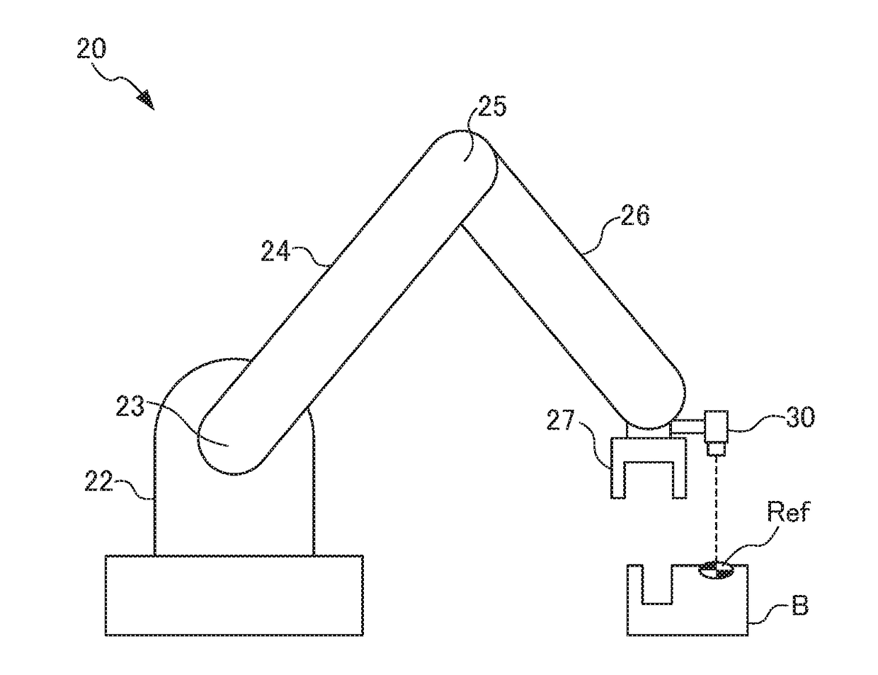
[0095]In the aforementioned embodiment, the reference point Ref such that it is possible to capture by the camera 30 is arranged beforehand on article A or article B, as explained by referencing FIGS. 6 to 9 in the section of . For example, as the reference point Ref, a visual mark such that can be captured by the camera 30 is pasted on article A or article B, respectively, as a sticker or the like. In addition, these reference points Ref and data corresponding thereto are stored to be associated as shown in Table 2, and correction of the operating program is performed using this data.

[0096]Herein, in a case such that the reference point corresponding to article A (hereinafter defined as “reference point RefA”) and the reference point corresponding to article B (hereinafter defined as “reference point RefB”) are at positions spaced by a certain extent, the camera 30 installed to the robot 20 operating based on the operating program will photograph the reference point RefA, then move...

application example of present embodiment

[0102]Next, an explanation will be made for an application example of the present embodiment by referencing FIG. 12. FIG. 12 illustrates the robot 20, stations 50a to 50f, and a traveling axis 40. A plurality of articles (for example, in the case of station 50a, articles a1 to a5) is arranged at the stations 50a to 50f.

[0103]Then, the robot 20 can move to each article of the respective stations 50 by moving along the traveling axis 40, and perform predetermined jobs at each station 50. Under such conditions, the robot 20 may perform similar jobs at each of the plurality of stations 50 at which similar articles are arranged.

[0104]In such a case, for the jobs at each of the respective stations 50, it is considered to generate an operating program corresponding to the respective job. However, since similar jobs are performed at each of the stations 50, it is wasteful to generate several of the same operating program. Therefore, the input of contents of the work procedure manual is acc...


PUM


Abstract

To perform a start-up operation of robots more simply than conventionally. A programming device includes: a program generation unit that generates a program for causing a predetermined operation passing through a plurality of movement destination points to be executed by a robot; a robot control unit that causes the predetermined operation to be executed by the robot according to control based on the program; an image acquisition unit that acquires a photographed image capturing a reference point that is arranged at a position having a predetermined relative relationship with a position of the movement destination point; and a movement destination point correction unit that corrects information of the movement destination point included in the program, based on the photographed image and the predetermined relative relationship, in which the robot control unit controls the robot based on corrected information of the movement destination point.

Description

[0001]This application is based on and claims the benefit of priority from Japanese Patent Application No. 2017-098861, filed on 18 May 2017, the content of which is incorporated herein by reference.BACKGROUND OF THE INVENTIONField of the Invention[0002]The present invention relates to a programming device and a robot control method for controlling a robot such as an industrial robot.Related Art[0003]Conventionally, a method called teaching playback for teaching to a robot has been widely employed. With teaching playback, predetermined operations are taught to a robot by moving the robot according to manipulations made by the user using a teaching control panel. Alternatively, predetermined operations are taught to a robot by the user directly pushing and pulling to move the robot. The robot generates an operating program for performing the predetermined operation based on these teachings. Then, by using this operating program, the robot can accurately repeat the predetermined opera...

Claims


Application Information

Patent Timeline
IPC IPC(8): B25J9/16B25J19/02
CPCB25J9/1697B25J9/1664B25J19/023B25J9/1612G05B2219/39484G05B2219/39527
Inventor BAN, KAZUNORI
Owner FANUC CORP
Why Eureka
Try Eureka