

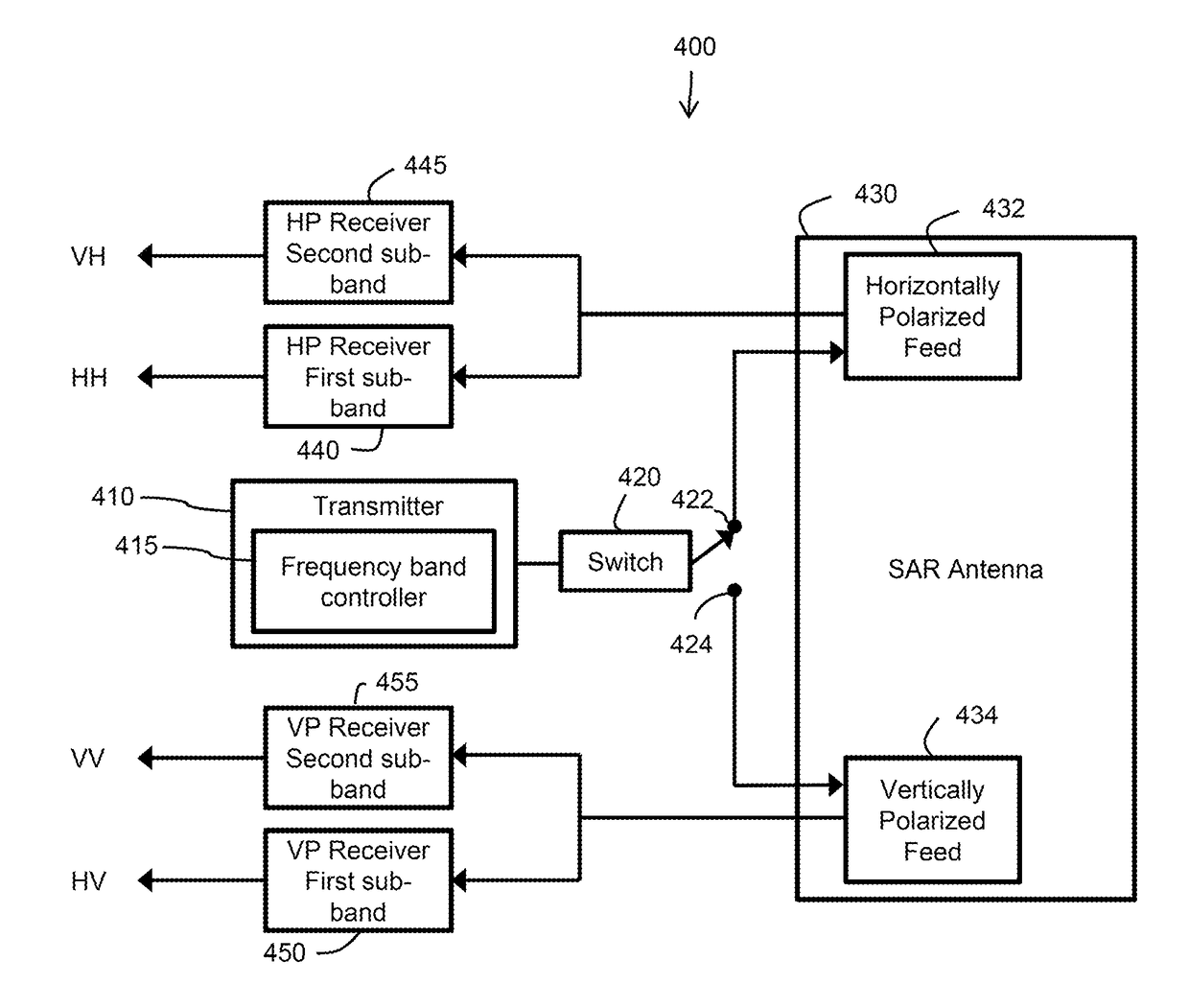
Apparatus and methods for quad-polarized synthetic aperture radar
a synthetic aperture radar and radar apparatus technology, applied in the field of synthetic aperture radar, can solve the problems of degrading image quality and scattering matrix accuracy, increasing range ambiguities, and increasing signal-dependent noise in the image, so as to reduce overall sar mass, volume and cost, and accurate determination of the polarization scattering matrix
- Summary
- Abstract
- Description
- Claims
- Application Information
AI Technical Summary
Benefits of technology
Problems solved by technology
Method used
Image

Examples
Embodiment Construction
Sub-Band Imaging Mode for Quad-Pol Sar
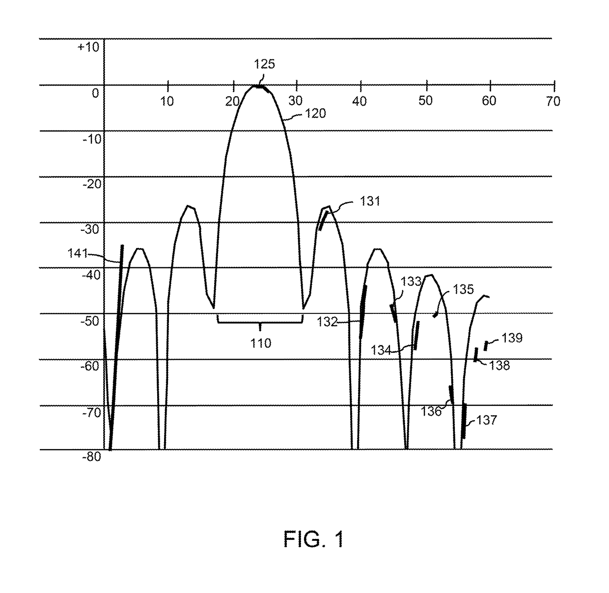
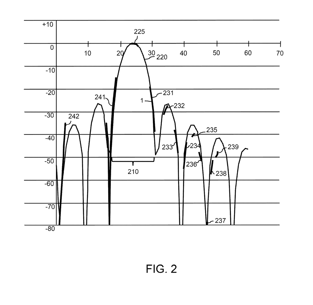
Range Ambiguities
[0029]It is well known that SAR suffers from the problems of range and azimuth ambiguities. Though range ambiguity can be addressed by simply not transmitting a second pulse until all returns from a first pulse have died out, in spaceborne SAR the problem is complicated by the long range to the ground.
[0030]The SAR data is generally sampled in azimuth at a rate somewhat larger than the azimuth Doppler bandwidth. The azimuth Doppler bandwidth can be reduced by increasing the azimuth (or along track) dimension of the antenna. Decreasing the azimuth sampling rate, or pulse repetition frequency (PRF), increases the spacing between range ambiguities, and the range ambiguity level decreases as the range ambiguities move further away from the peak of the antenna pattern.
[0031]FIG. 1 is a graph illustrating range ambiguities separated from the main lobe 110 of an antenna pattern 120. The example shown in FIG. 1 is for an L-band radar sy...
PUM
 Abstract
Description
Claims
Application Information