
Surgical Probe

a surgical and probe technology, applied in the field of surgical probes, can solve the problems of increasing the surgical duration, increasing the surgical time, so as to facilitate the assembly of the probe, improve the reliability of the probe, and improve the effect of the ar

Inactive Publication Date: 2018-11-29
FALKE MEDICAL SAGL
View PDF2 Cites 1 Cited by
  • Summary
  • Abstract
  • Description
  • Claims
  • Application Information

AI Technical Summary

Benefits of technology

The present invention proposes a surgical probe that overcomes the drawbacks of the prior art. The probe has improved reliability and easier assembly. It includes a thrust transmission section that has higher mechanical stiffness than the flexible section. The actuation transmission mechanism is provided as a sheet of material that allows for displacement of the blade in the plane of the blade. The blade is laterally guided to prevent tilting. The cross sectional shape of the shaft is suitable for enclosing internal functional components of the probe. The housing has a minimized cross sectional dimension that allows for the actuation mechanism and other internal functional components to be provided alongside each other.

Problems solved by technology

As is readily appreciated, these mechanisms are expensive to assemble and provide inside the cavity of the housing with a restricted cross sectional dimension.
Moreover, there might be an imminent danger of the miniature pivoting connections blocking or otherwise failing, which might force replacement of the probe, and in turn extension of the surgery duration and additional trauma to the patient.
It is moreover apparent that a complex assembly as disclosed in U.S. Pat. No. 8,951,273 may be tough to clean after assembly.

Method used


Image

  • Surgical Probe
  • Surgical Probe
  • Surgical Probe

Examples


Embodiment Construction

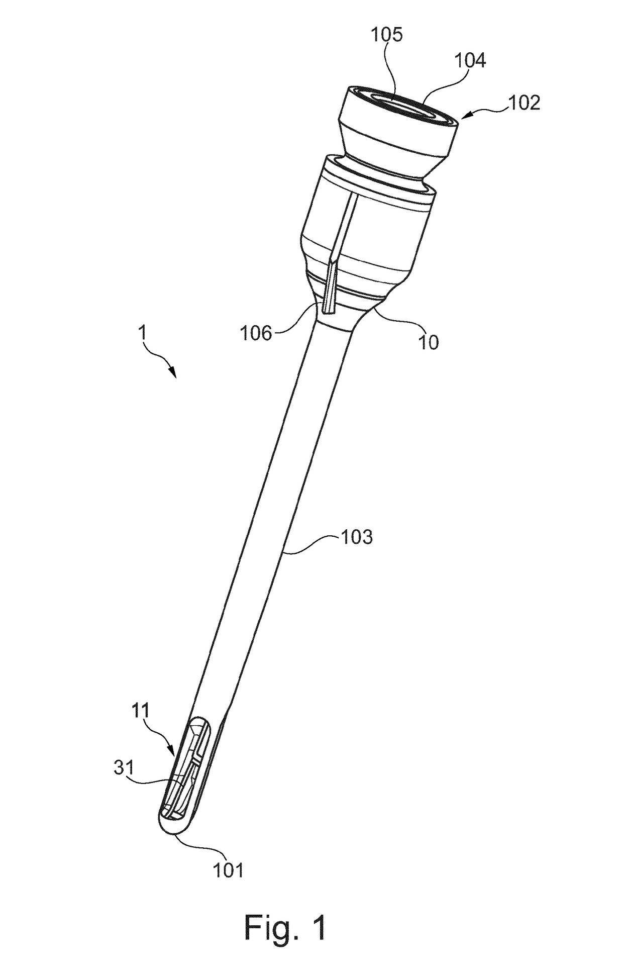
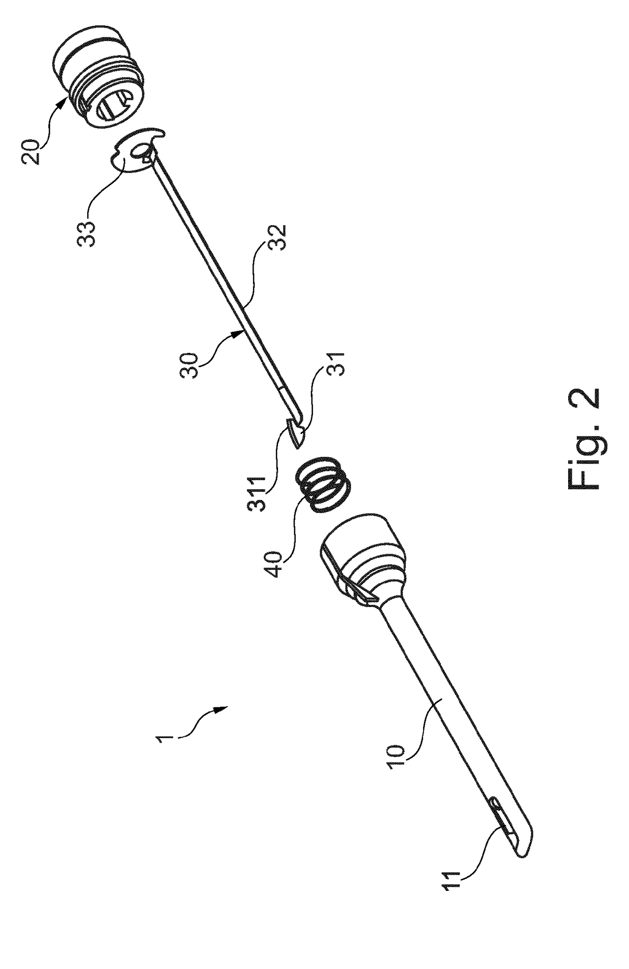
[0056]FIG. 1 depicts an exemplary embodiment of a surgical probe 1. Surgical probe 1 includes a distal end or tip 101 and a proximal end 102. A connection interface 104 is provided at the proximal end of surgical probe 1. Through connection interface 104, probe 1 may be releasably connected to an instrument handle. The instrument handle may, in a well-known manner, include an actuator for operating and manipulating an instrument including the instrument handle and the probe. The actuation function, and other optional features and functional properties of the handle, will become more apparent in the light of the specification below. Housing 10 includes and forms a shaft 103 of surgical probe 1 and extends to distal end 101. A longitudinal cavity, not visible in the present depiction, extends inside the housing along a proximal-distal extent. The cavity has an open proximal front face 105 at the proximal end of the surgical probe, and is closed at a distal front face. The longitudinal...


PUM


Abstract

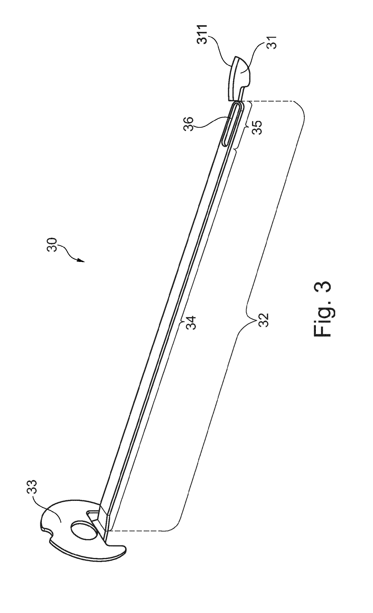
A surgical probe has a housing (10) extending along a longitudinal extent from a proximal end to a distal end. A longitudinal cavity (14) is provided inside the housing and extends along a proximal-distal direction inside the housing, the cavity being open at a proximal front face and being closed at a distal front face. The housing includes an aperture (11) provided in a distal region of the housing and through which the longitudinal cavity is in communication with the exterior of the housing at a circumferential position of the housing, such that the longitudinal cavity (14) is open at a circumferential position through the aperture (11). A blade (31) has a cutting edge (311) and an actuation transmission mechanism (32) inside the housing and in the longitudinal cavity, and the blade (31) is disposed distal of the actuation transmission mechanism (32). The blade is displaceable in the cavity such as to move the blade between a retracted position in which the blade is entirely contained inside the housing and an operative position in which the cutting edge of the blade is provided at least partially outside the housing. The actuation transmission mechanism is operatively connected to the blade such that an actuation of the actuation transmission mechanism causes displacement of the blade, wherein the blade (31) and the actuation transmission mechanism (32) are integrally provided with each other to form an integral blade unit. The probe may in particular be suitable for hand surgery, for an instance for carpal tunnel, trigger finger or de Quervain's tenosynovitis release

Description

[0001]This application is a Continuation of, and claims priority under 35 U.S.C. § 120 to, International Application No. PCT / EP2016 / 079687, filed 2 Dec. 2016, and claims priority therethrough to European App. No. 15197865.7, filed 3 Dec. 2015, and to European App. No. 16182478.4, filed 2 Aug. 2016, the entireties of which are incorporated by reference herein.BACKGROUNDField of Endeavor[0002]The present disclosure relates to a surgical probe.Brief Description of the Related Art[0003]For a variety of surgical procedures, for instance in hand surgery, and for more particular instances carpal tunnel, trigger finger or de Quervain's tenosynovitis release, or comparable surgical procedures, probes are required which may be introduced into a narrow longitudinal lumen of the body. Surgery is performed essentially inside that lumen. To this extent, for instance from U.S. Pat. No. 8,523,891, WO 2008 / 098251, U.S. Pat. No. 5,306,284, and U.S. Pat. No. 8,951,273 surgical probes are known which c...

Claims


Application Information

Patent Timeline
IPC IPC(8): A61B17/32A61B90/00
CPCA61B17/320036A61B90/361A61B2017/00738
Inventor PAJARDI, GIORGIOEPPER, MARTINCHERUBINO, TOMMASO
Owner FALKE MEDICAL SAGL
Learn More