Control apparatus

a control apparatus and control technology, applied in the direction of power conversion systems, dc-dc conversion, instruments, etc., can solve the problems of low accuracy of magnetization bias prediction, low accuracy of current detection device, and inability to accurately correct so as to prevent offset errors, reduce the magnetization bias of the transformer, and achieve the effect of appropriately reducing the magnetization bias

Active Publication Date: 2018-11-29
SOKEN CO LTD +1
View PDF0 Cites 7 Cited by
  • Summary
  • Abstract
  • Description
  • Claims
  • Application Information

AI Technical Summary

Benefits of technology

[0009]In the case where a magnetization bias has occurred on the transformer, current flowing through the rectifier circuit during a period in which each of the first input switch and the second input switch turn ON is varied because of an influence of the magnetization bias. Also, an offset error which is a DC (direct current) component superposed on the detection value of the current sensor is constant regardless of the offset error. Hence, according to the present application, the first current is acquired as the detection value of the current sensor during an ON period where the first input switch turns ON, and the second current is acquired as the detection va

Problems solved by technology

In the case where an amount of the magnetization bias is predicted by using the current detection device as disclosed in the above-described patent literature, the current detected by the current detection device may include offset errors.
H

Method used


Image

  • Control apparatus
  • Control apparatus
  • Control apparatus

Examples


first embodiment

Modification of First Embodiment

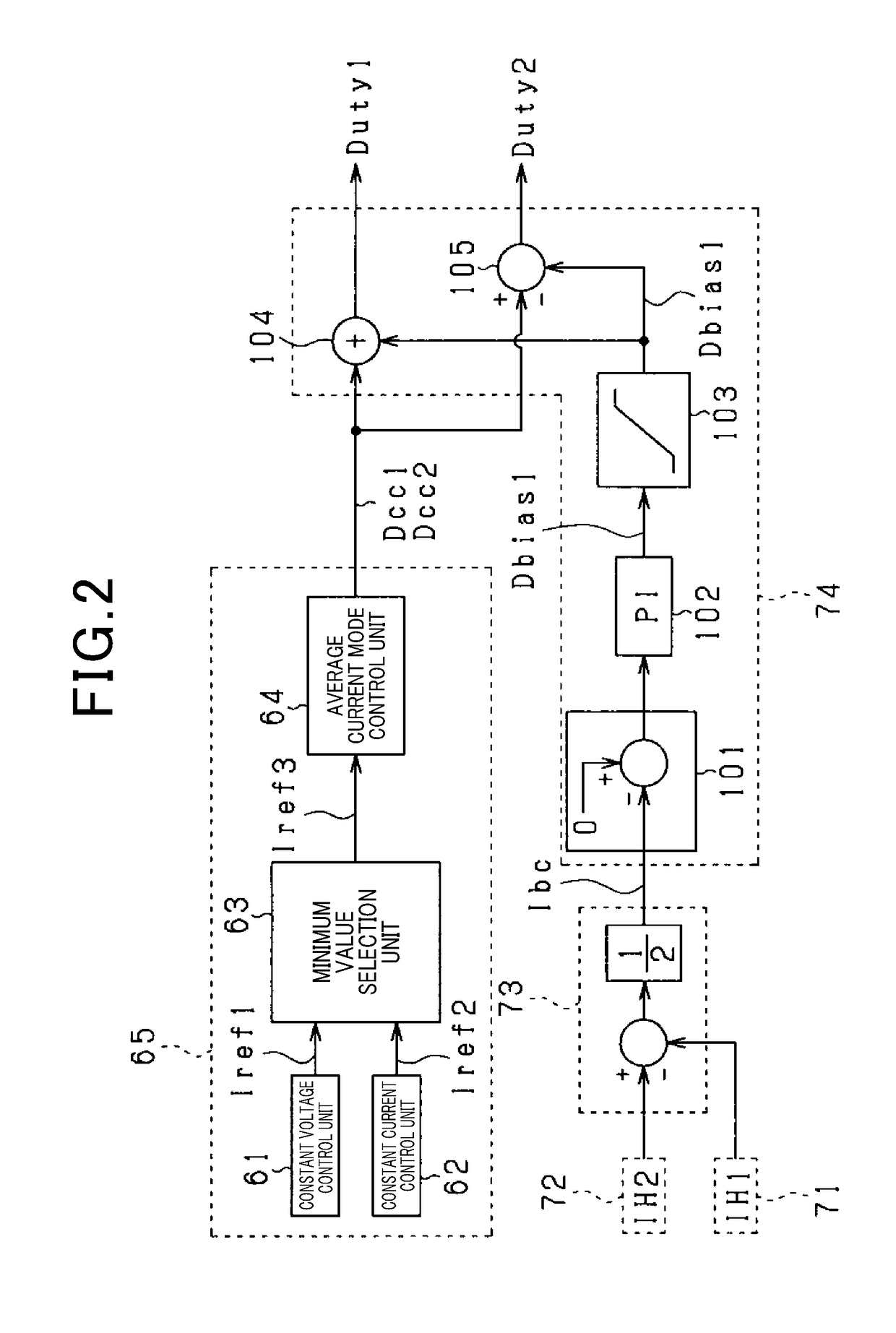
[0097]The prediction unit 73 shown in FIG. 2 may calculate a deviation between the first current IH1 and the second current IH2 and output the deviation. In this case, the PI control unit 102 may calculate the first correction value Dbias as a control input used for a feedback control to control the calculated deviation to be 0.

second embodiment

[0098]According to the second embodiment, configurations different from that of the first embodiment will mainly be described.

[0099]According to the second embodiment, the control unit 60 performs a peak current mode control in which OFF timings of the first and second switches Q1 and Q2 are set based on the peak value of the primary side current IL flowing through the first circuit 40.

[0100]FIG. 8 is a functional block diagram illustrating a function of a peak current mode control in functions of the control unit 60. In FIG. 8, the primary side setting unit 65 is provided with a first peak current mode control unit 67 that sets the first drive command value Dcc1 of the first switch Q1, and a second peak current mode control unit 68 that sets the second drive command value Dcc2 of the second switch Q2.

[0101]The first peak current mode control unit 67 is provided with a DA converter 341, a comparator 342, an adder 343, a RS flipflop 347, and a Duty limiting unit 348. First, the comma...

third embodiment

Modification of Third Embodiment

[0138]In the third embodiment, the ON periods of the third to sixth switches Q3 to Q6 may be adjusted with the B mode. In the B mode in which the first and second switches Q1 and Q2 are both ON, the secondary winding voltage Vt is not exactly 0 so that current flows through the second circuit 50. Hence, even in the B mode, by adjusting the ON periods of the third to sixth switches Q3 to Q6, the secondary winding voltage Vt can be adjusted.

[0139]FIGS. 14A to 14F are an operation sequence illustrating a reduction process of the transformer 30 according to the modification. In FIGS. 14A to 14F, the ON periods of the third and sixth switches Q3 and Q6 are extended to the B mode from the A mode. Also, the ON periods of the fourth and fifth switches Q4 and Q5 are extended to the B mode from the C mode. Therefore, during the ON periods of the third and sixth switches Q3 and Q6 in the B mode, the secondary winding voltage Vt increases by a voltage difference ...


PUM


Abstract

A control unit capable of accurately calculating a magnetization bias of a transformer is provided, thereby appropriately reducing the magnetization bias. The control unit acquires first and second currents that flow through a transformer during a period where either first or second switches individually turn ON. The control unit predicts an amount of magnetization bias in either positive side or negative side of the excitation current that flows through the transformer. The control unit reduces the magnetization bias of the transformer based on the predicted amount of magnetization bias.

Description

CROSS-REFERENCE TO RELATED APPLICATION[0001]This application is based on and claims the benefit of priority from earlier Japanese Patent Application No. 2017-102885 filed May 24, 2017, the description of which is incorporated herein by reference.BACKGROUNDTechnical Field[0002]The present disclosure relates to a control apparatus that suppresses the magnetization bias of a transformer.Description of the Related Art[0003]Conventionally, a power conversion apparatus in which a primary circuit and a secondary circuit are connected through a transformer is known. According to the above-mentioned power conversion apparatus, magnetization bias may occur on the transformer in which magnetic flux is biased. The magnetization bias of the transformer can be predicted using an amount of deviation in the excitation current which produces the magnetic flux in the transformer.[0004]In this respect, Japanese Patent Application Laid-Open Publication Number 2016-192889 discloses a power conversion sy...

Claims


Application Information

Patent Timeline
IPC IPC(8): H02M1/08H02M3/335
CPCH02M3/33576H02M2001/0009H02M3/33507H02M1/0009
Inventor IYASU, SEIJIHAYASHI, YUJIHANDA, YUICHI
Owner SOKEN CO LTD
Why Eureka
Try Eureka