
Disinfecting conveyor system

a conveyor system and disinfecting technology, applied in the direction of disinfection, water installations, construction, etc., to achieve the effect of reducing the humidity level of the process air, preventing the growth of bacteria, and reducing the growth of bacteria

Inactive Publication Date: 2018-12-06
RADIANT IND SOLUTIONS LLC
View PDF0 Cites 18 Cited by
  • Summary
  • Abstract
  • Description
  • Claims
  • Application Information

AI Technical Summary

Benefits of technology

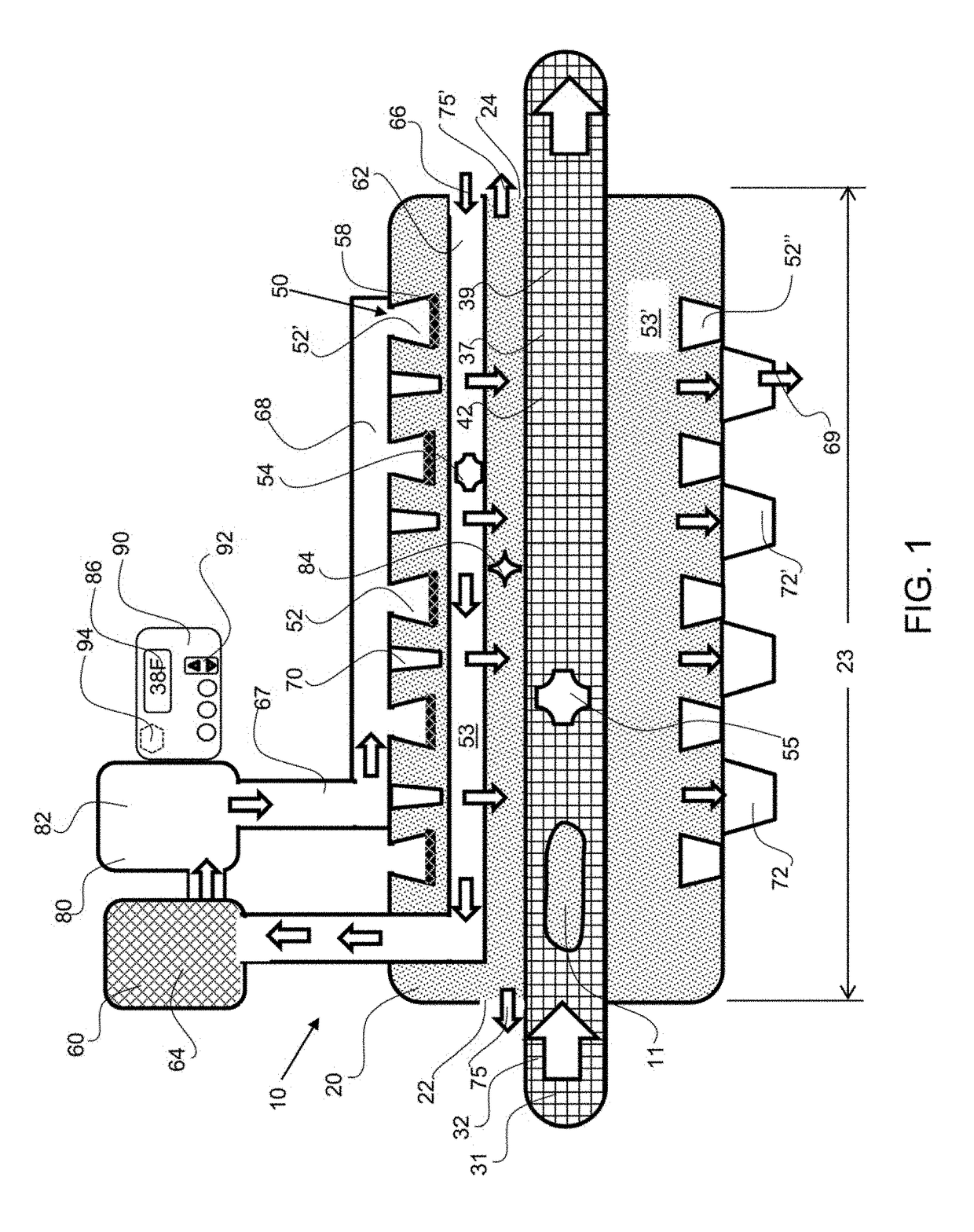
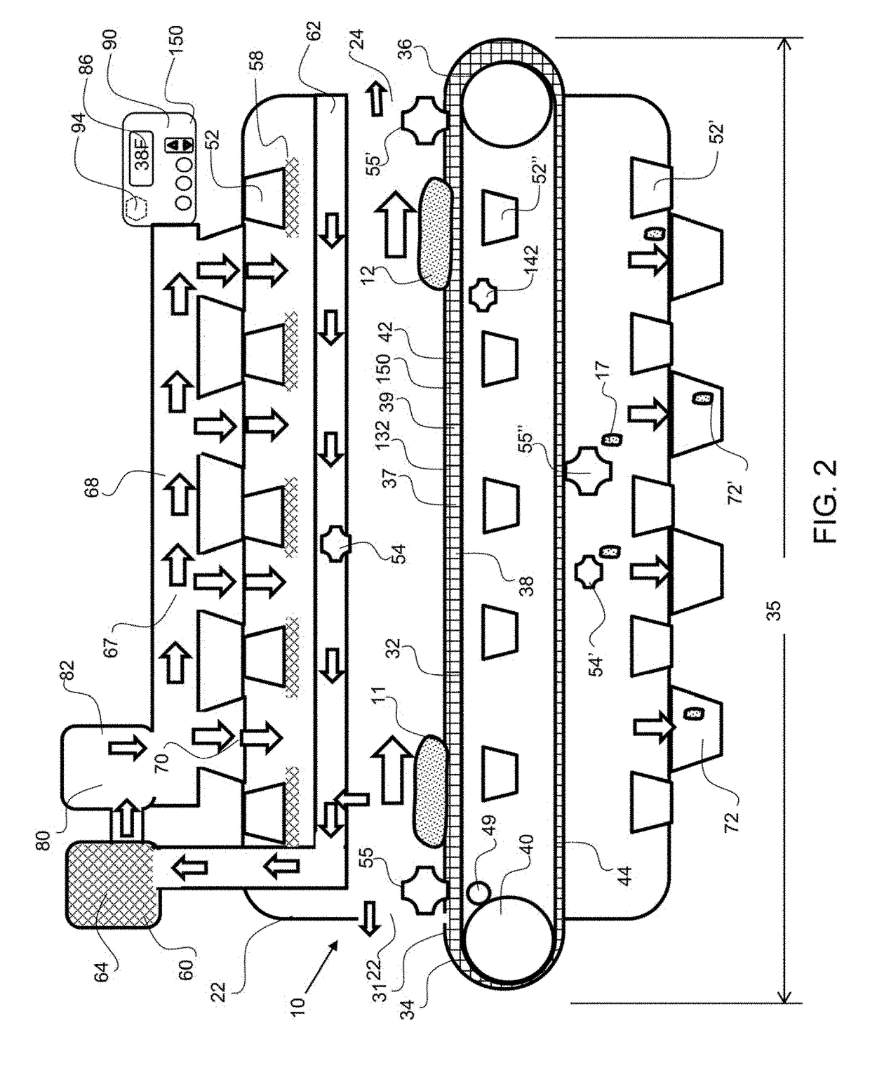
The patent describes a disinfecting conveyor system that uses air inlet vents to create a uniform and laminar flow of air over the product, which prevents unwanted stirring of the air or removal of debris from the product. A replaceable plastic or quartz liner is used to ensure that bacteria or other microorganisms do not grow within the enclosure or contaminate the product. A separator may be used to prevent debris from falling down onto the product, and the humidity level of the process air can be controlled to prevent bacteria growth. The system also uses UV light and ozone gas to disinfect the product. Overall, the system creates a safe and sanitary environment for the production process.

Problems solved by technology

UV light can interfere with an organisms' metabolic system and reproductive processes, rending the organism no longer pathogenic.

Method used


Image

  • Disinfecting conveyor system
  • Disinfecting conveyor system
  • Disinfecting conveyor system

Examples


Embodiment Construction

[0026]Corresponding reference characters indicate corresponding parts throughout the several views of the figures. The figures represent an illustration of some of the embodiments of the present invention and are not to be construed as limiting the scope of the invention in any manner. Further, the figures are not necessarily to scale, some features may be exaggerated to show details of particular components. Therefore, specific structural and functional details disclosed herein are not to be interpreted as limiting, but merely as a representative basis for teaching one skilled in the art to variously employ the present invention.

[0027]As used herein, the terms “comprises,”“comprising,”“includes,”“including,”“has,”“having” or any other variation thereof, are intended to cover a non-exclusive inclusion. For example, a process, method, article, or apparatus that comprises a list of elements is not necessarily limited to only those elements but may include other elements not expressly ...


PUM


Abstract

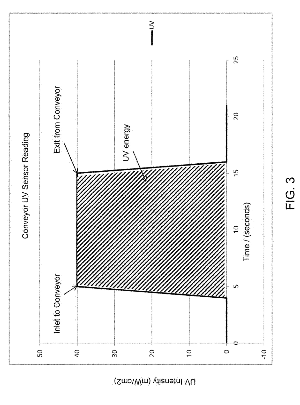
A disinfecting conveyor system utilizes ultraviolet light to disinfect a product as it passes through an enclosure on a conveyor. A UV light sensor provides feedback to a control system that can change the amount of UV light exposure, speed of conveyor, and disinfection reaction. A UV light sensor may be a coupled to the conveyor and the UV light intensity and time of exposure within the enclosure may be used to calculate a UV light dose. A user of the system may input a required UV light dose or the type of product to be disinfected and the control system may automatically control the speed of the conveyor and / or the UV light intensity to provide the required UV dose. The system may utilize an air filtration and / or cooling system to provide a flow of clean and cool process air to the enclosure to maintain a temperature that is below a threshold temperature.

Description

CROSS REFERENCE TO RELATED APPLICATIONS[0001]This application is a continuation in part of PCT / US2017 / 016272, filed on Feb. 2, 2017 which claims the benefit of priority to U.S. provisional patent application No. 62 / 289,990 filed on Feb. 2, 2016, and this application also claims the benefit of priority to U.S. provisional patent application No. 62 / 662,884, filed on Jun. 8, 2018; wherein all applications are entitled Disinfecting Conveyor System; and wherein the entirety of all prior applications are hereby incorporated by reference herein.BACKGROUND OF THE INVENTIONField of the Invention[0002]This invention relates to the conveyance or transport through conveyor systems for disinfecting products including foods, containers, or food touch materials as they pass through the conveyor. The objective is to create a sanitizing environment where the food, container, or product is not altered by the intervening technology.Background[0003]Conveyor systems for disinfecting products, including ...

Claims


Application Information

Patent Timeline
IPC IPC(8): A23L3/28A61L2/10A61L2/26
CPCA23L3/28A61L2/10A61L2/26A61L2/24A61L2202/11A61L2202/122A61L2202/14A61L2202/23A23L3/001
Inventor ALZEER, MOHAMMEDBARTLETT, TIMJAWORSKI, DREWGUERRETTE, MICHAEL R.SMITH, TROY
Owner RADIANT IND SOLUTIONS LLC
Learn More