Forced air circulation for centrifugal pellet dryer

a centrifugal pellet dryer and air circulation technology, which is applied in the direction of drying machines, drying solid materials without heat, lighting and heating apparatus, etc., can solve the problems of increasing the humidity level of the internal dryer air, inconvenient use, and inability to meet the needs of the user, so as to reduce the water spray, improve the drying efficiency, the effect of effectiveness and capacity

Inactive Publication Date: 2005-03-10
CARTER DAY INDS
View PDF13 Cites 15 Cited by
  • Summary
  • Abstract
  • Description
  • Claims
  • Application Information

AI Technical Summary

Benefits of technology

[0007] An object and advantage of the invention is to provide a centrifugal pellet dryer with increased drying efficiency, effectiveness and capacity.
[0008] Another object and advantage of the invention is to provide a centrifugal pellet dryer that reduces the waterspray within the dryer and lowers the humidity level in the dryer.
[0009] Another object and advantage of the invention is to introduce either ambient or preheated forced dry air into the dryer system to enhance the dryer's effectiveness.
[0010] Yet another object and advantage of the invention is to provide exposure of the product to the dry forced air for as long a period as possible to enhance the dryer's effectiveness.

Problems solved by technology

These known systems, however, may include a “dried” product that may have an unacceptable level moisture at the end of the process and require further drying to meet the requisite specification.
This is due to a significant amount of spray in the water removal space which may result in some water being reintroduced into the product and an increase in the humidity level of the internal dryer air.
In general, the known dryer is relatively inefficient and, as a result, has a capacity which may be greatly improved.

Method used


Image

  • Forced air circulation for centrifugal pellet dryer
  • Forced air circulation for centrifugal pellet dryer
  • Forced air circulation for centrifugal pellet dryer

Examples


Embodiment Construction

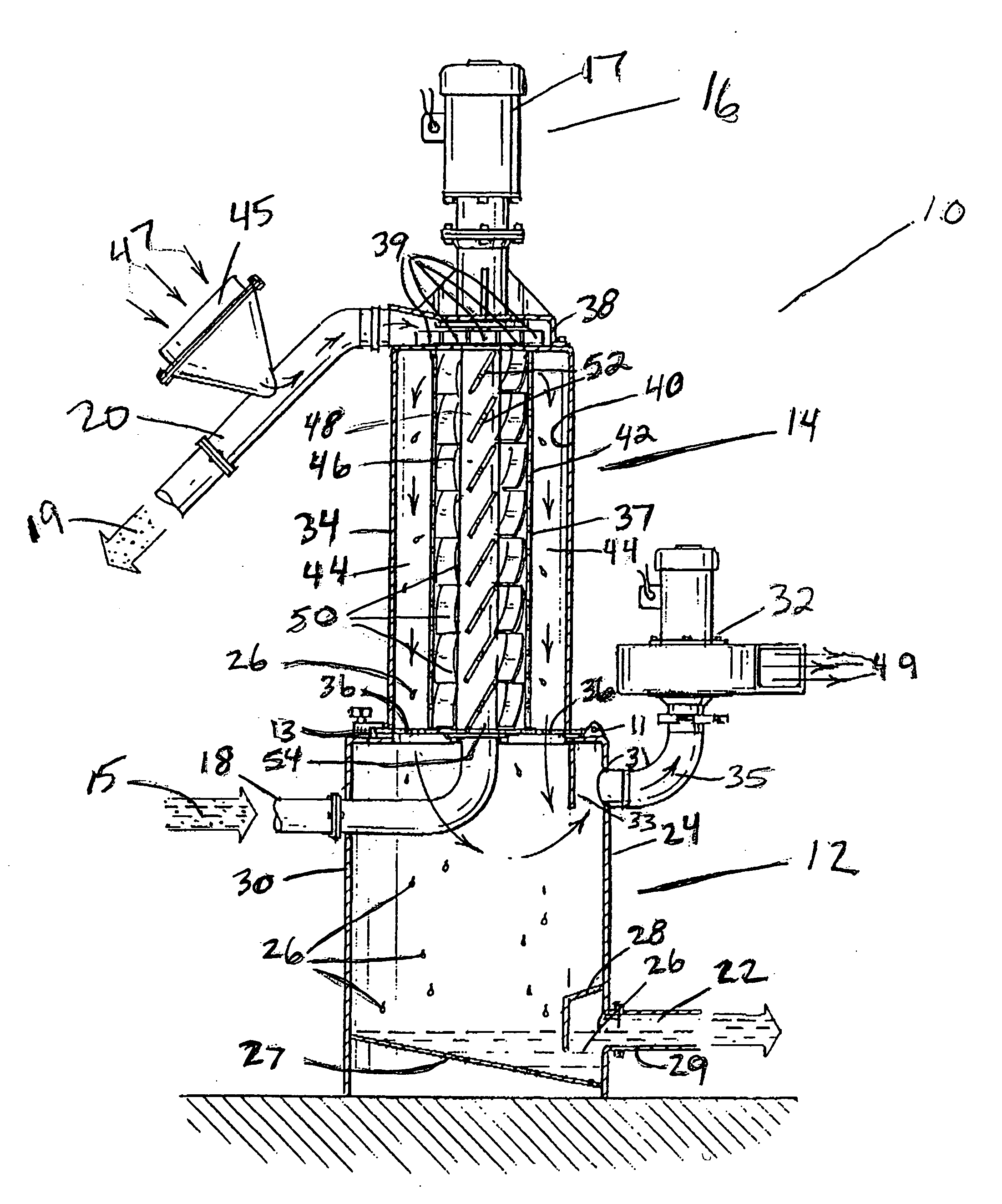
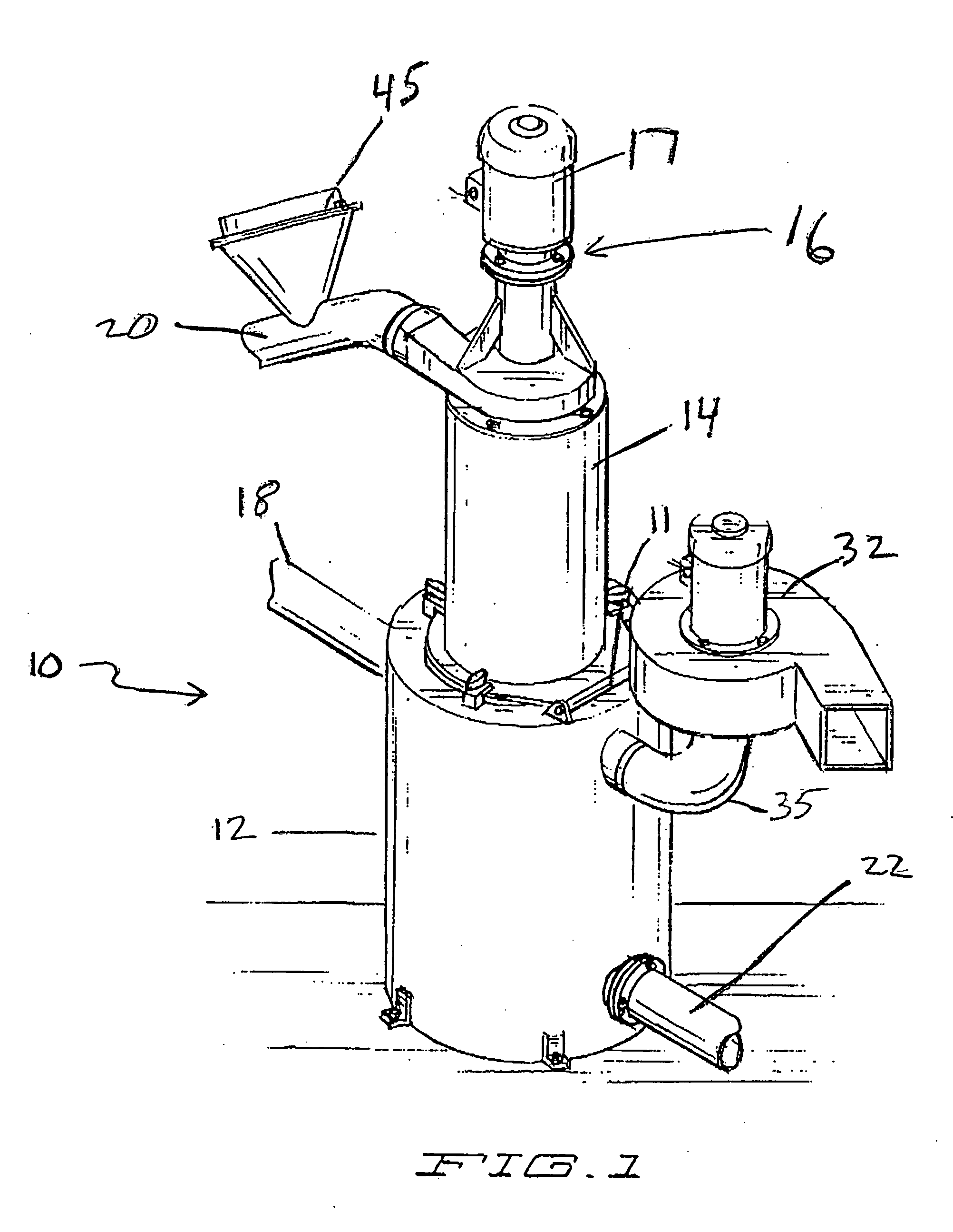
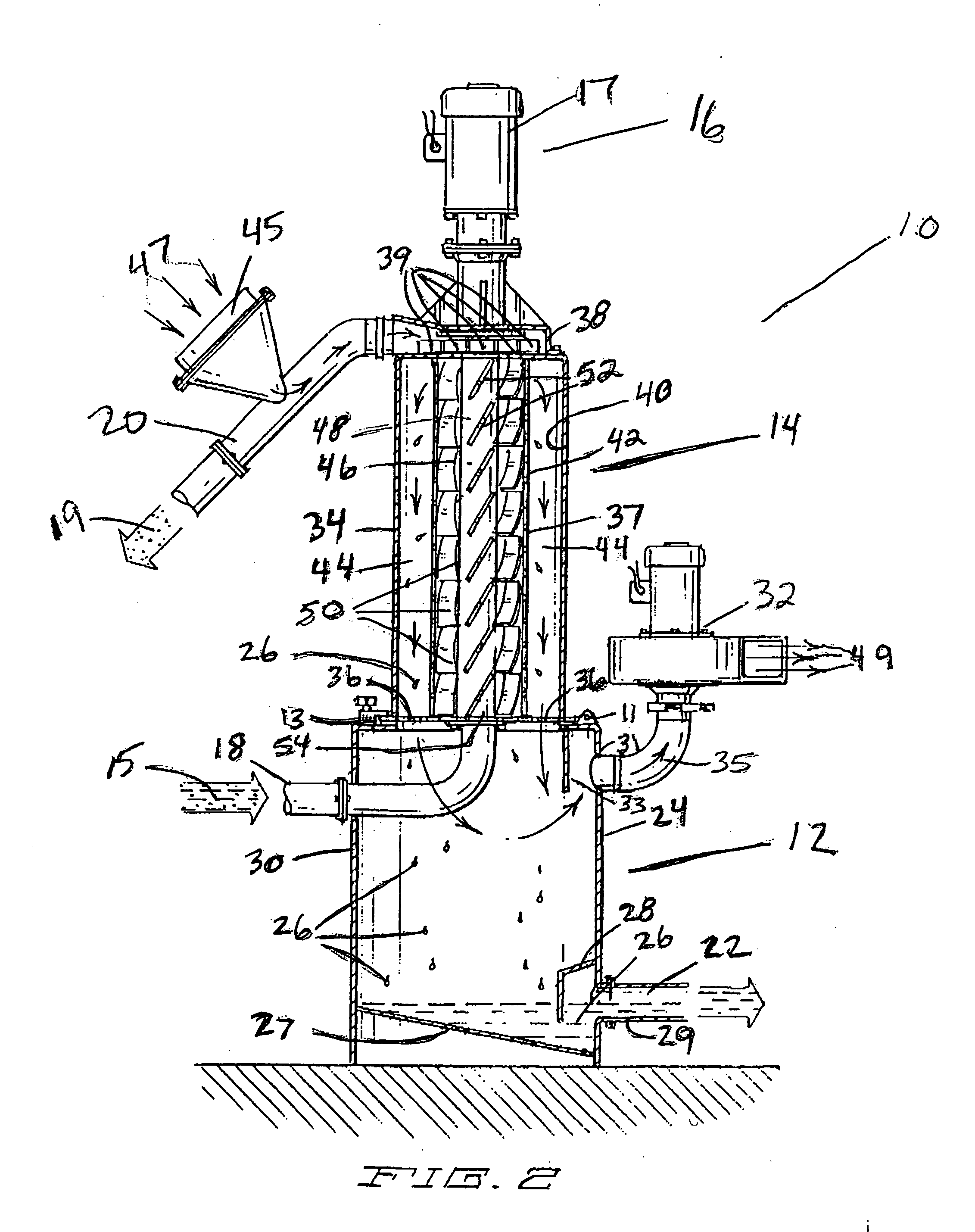
[0014] With reference to the accompanying Figure, which provides one embodiment of the invention, there is provided an improved centrifugal pellet dryer with increased drying effectiveness, efficiency and capacity.

[0015] A centrifugal dryer in accord with the present invention 10 is shown in FIGS. 1 and 2. Dryer 10 includes a reservoir section 12, a dryer section 14, and a motor section 16. A product slurry 15, such as a plastic bead or sphere / water mixture, is introduced into the dryer 10 by means of an inlet pipe 18. As best illustrated in FIG. 2, inlet pipe 18 introduces the product slurry into the center of the dryer section 14 and along the axis of rotation of the rotor 46. The center inlet for the slurry 15 provides additional suction and capacity, making the operation of the motor more efficient and providing a more efficient initial water discharge from the product. Dried product 19 is removed from the dryer 10 through a product discharge chute 20 while water removed from t...


PUM

PropertyMeasurementUnit
angleaaaaaaaaaa
volumeaaaaaaaaaa
axis of rotationaaaaaaaaaa

Abstract

An improved centrifugal pellet dryer that employs forced air in the direction opposite that of the pellet travel through the dryer. The air may be preheated depending on the particular product. The resulting airstream reduces water spray and lowers the humidity level of the air in the dryer system. The airstream exits the dryer at or below the lower level of the rotor, thus providing increased exposure to the airflow. The result is enhanced drying effectiveness and increased dryer capacity.

Description

FIELD OF THE INVENTION [0001] This invention relates generally to centrifugal pellet dryers. BACKGROUND OF THE PRESENT INVENTION [0002] Raw plastics manufacturers produce a liquid product that is extruded in a tubular form from an extruder. The product is extruded under water and then cut into small pieces, tending to form generally spherically shaped particles or beads as it cools. This plastic bead / water slurry is then transported to a dryer to remove the water from the plastic product so that the product can be shipped to other manufacturers to manufacture useful products. [0003] Before shipment, the raw plastic product must be dried. This has been accomplished in the past with the use of centrifugal dryers. Such dryers are known in the art. Typically such dryers force water from the product by striking the water-laden product against a screen, forcing the water through the screen and into a water collection space, thus allowing gravity to drive the water downwardly into a water ...

Claims


Application Information

Patent Timeline
Patent Type & Authority Applications(United States)
IPC IPC(8): F26B5/08F26B7/00F26B17/24
CPCF26B5/08B29B9/16F26B17/24F26B7/00
Inventor HAUCH, DAVID
Owner CARTER DAY INDS
Why Eureka
Try Eureka