Air flow control device for an engine block in a motor vehicle

a technology of air flow control and engine block, which is applied in the direction of engine cooling apparatus, mechanical apparatus, component optimization, etc., can solve the problems of significant drag force, slow vehicle, complex opening and closing kinematics of such a device with an array of slats, etc., and achieves optimal longevity, simple and robust parts, and effective cooling of the engine of the vehicle

Active Publication Date: 2018-12-06
FLEX N GATE GERMANY GMBH
View PDF4 Cites 1 Cited by
  • Summary
  • Abstract
  • Description
  • Claims
  • Application Information

AI Technical Summary

Benefits of technology

[0016]One aim of the invention is to effectively cool the engine of the vehicle without increasing the quantity o

Problems solved by technology

Furthermore, when the speed of the vehicle is significant, the air flow in the aeration duct is high enough to disrupt the flow of air in the location where it is discharged from the vehicle and to create a significant drag force, which may slow the vehicle.
Indeed, the opening and closing kinematics o

Method used


Image

  • Air flow control device for an engine block in a motor vehicle
  • Air flow control device for an engine block in a motor vehicle
  • Air flow control device for an engine block in a motor vehicle

Examples


first embodiment

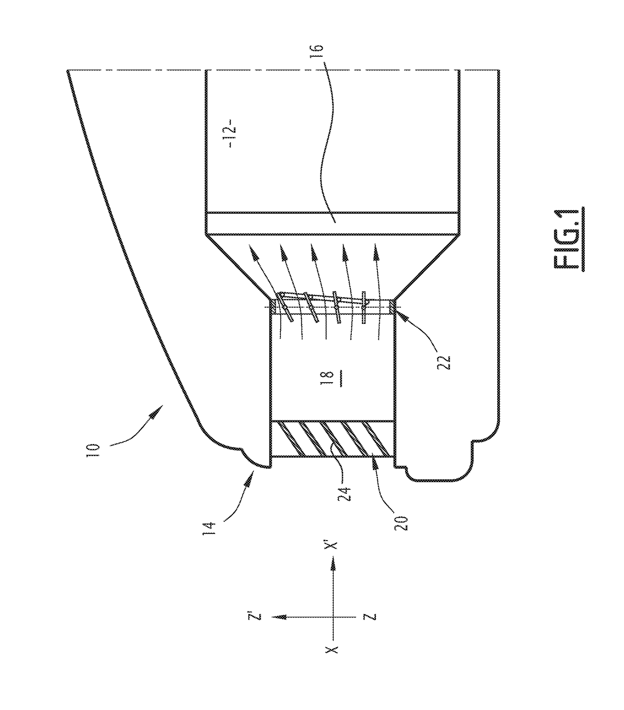
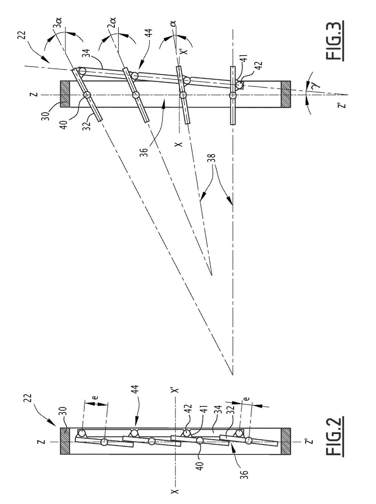
[0041]The device 22 is suitable for controlling the air flow flowing in the duct 18 toward the radiator 16. the device 22 is shown in detail in FIGS. 2 and 3.

[0042]The device 22 comprises a frame 30, a plurality of slats 32 arranged across the frame 30, and an actuator 34 of the slats 32. In the illustrated example, the device 22 comprises four identical slats 32. Alternatively, the device 22 comprises another number of slats 32, for example between two and twelve slats 32.

[0043]The frame 30 is a substantially rectangular structure, which extends along the walls of the duct 18 along a transverse plane YZ orthogonal to the flow axis of the air X-X′. The frame 30 defines an opening 36 with a substantially rectangular section in the transverse plane YZ, such that the opening 36 extends across the frame 30, along the air flow axis X-X′.

[0044]The slats 32 extend through the frame 30 in a transverse direction Y-Y′ substantially orthogonal to the air flow axis X-X′. The slats 32 are arrang...

second embodiment

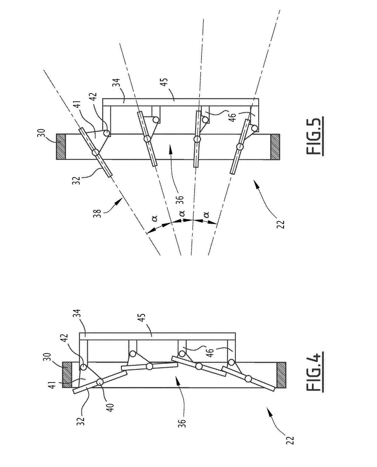
[0067]In the second embodiment, the actuator 34 does not deform significantly when the slats 32 go from the closed position shown in FIG. 4 to the open position shown in FIG. 5.

[0068]In the second embodiment, the slat axes 40 are not aligned in a direction parallel to the transverse plane YZ, but are arranged along a curved line, for example with the slat axes 40 of the second and third slats 32 located further downstream than the slat axes 40 of the first and fourth slats 32.

[0069]Furthermore, the actuating axes 42 of the slats 32 are arranged along a same curved line, translated when the slats 32 go from the open position to the closed position and vice versa. In other words, each of the actuating axes 42 follows the same translation when the slats 32 are moved from the open position to the closed position or vice versa.

[0070]In the illustrated example, the actuator 34 comprises a main segment 45 and a plurality of secondary segments 46 connected substantially orthogonally to the ...


PUM


Abstract

A device for controlling an air flow in a motor vehicle compartment. The device includes: a frame defining an opening; a plurality of slats extending across the frame, arranged above one another; and an actuator connected to each of the slats by a respective fastener. Each slat extends in a respective air deflection plane, and is movable via the actuator, between: a closed position, in which the slats cooperate with one another to block the passage of the air through the opening, and an open position, in which the slats allow the air to flow through the opening, the deflection planes of the slats intersecting upstream from the frame. Each fastener is mounted rotatably only on the actuator, around a respective actuating axis.

Description

TECHNICAL FIELD[0001]The present invention relates to an air flow control device in a motor vehicle compartment, the device comprising:[0002]at least one frame defining an opening, the frame extending in a transverse plane, the opening extending along a flow axis of the air substantially perpendicular to the transverse plane;[0003]a plurality of slats extending across the frame, the slats being arranged above one another; and[0004]an actuator connected to each of the slats by a respective fastener;[0005]each slat extending in a respective air deflection plane, and each slat being movable relative to the frame around a respective slat axis, using the actuator, between:[0006]a closed position, in which the slats cooperate with one another to block the passage of the air through the opening, and[0007]an open position, in which the slats allow the air to flow through the opening, and in which the deflection planes of the slats intersect one another upstream from the frame relative to th...

Claims


Application Information

Patent Timeline
IPC IPC(8): F01P11/10F01P3/18B60K11/08B60K11/06
CPCF01P11/10F01P3/18B60K11/085B60K11/06Y02T10/88
Inventor CLAPIE, YANNTHOULOUZE, BERTRANDEICHLINGER, DANIEL
Owner FLEX N GATE GERMANY GMBH
Why Eureka
Try Eureka