Thermostat monitoring system and method

a technology of monitoring system and thermostat, applied in the direction of heat measurement, instruments, machines/engines, etc., can solve the problem of difficulty in developing such a model with enough accuracy to be robus

Active Publication Date: 2018-12-06
NISSAN MOTOR CO LTD
View PDF6 Cites 3 Cited by
  • Summary
  • Abstract
  • Description
  • Claims
  • Application Information

AI Technical Summary

Benefits of technology

[0003]Current regulations require accuracy in the monitoring and diagnosing of thermostat operations after engine warms up. To meet the new regulation requirements, a new engine coolant temperature estimation model used to compare with measured temperatures is needed. It is, however, very difficult to develop such a model with enough accuracy to robustly detect thermostat failure without any false detection.

Problems solved by technology

It is, however, very difficult to develop such a model with enough accuracy to robustly detect thermostat failure without any false detection.

Method used


Image

  • Thermostat monitoring system and method
  • Thermostat monitoring system and method
  • Thermostat monitoring system and method

Examples


first embodiment

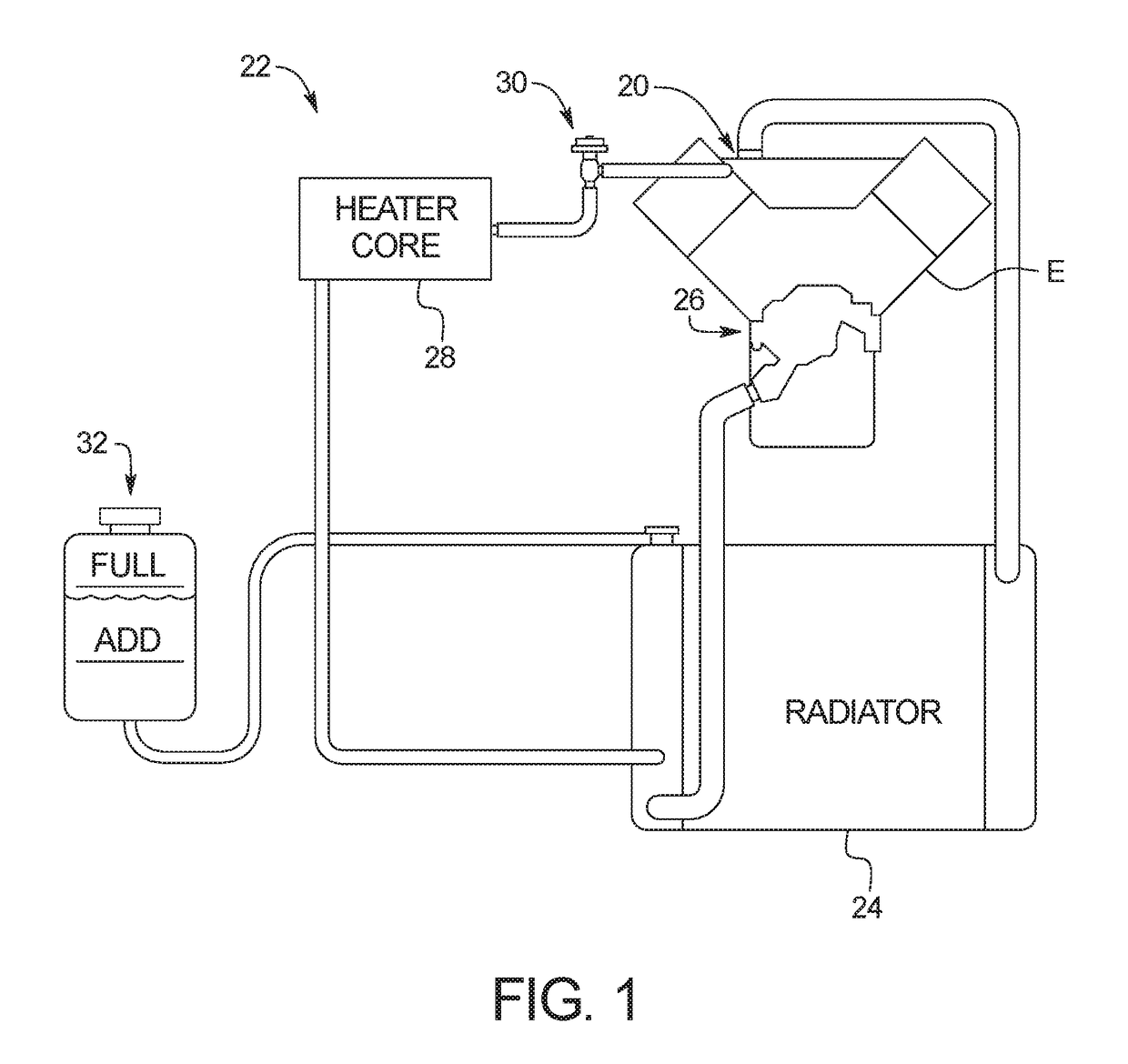
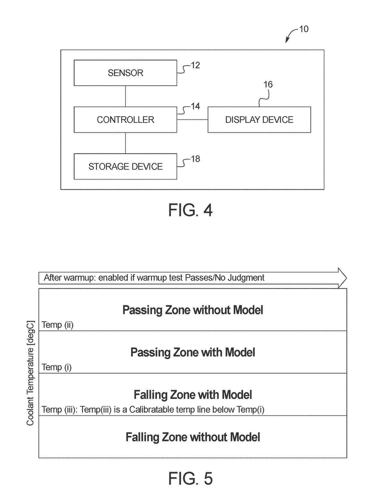
[0028]Referring initially to FIGS. 1-4, an engine thermostat monitoring system 10 is illustrated in accordance with a As can be seen, the engine thermostat monitoring system 10 includes a sensor 12, a controller 14, a display device 16 and a storage device 18 and monitors a thermostat 20 in an engine cooling system 22, generally of a vehicle, by monitoring the engine coolant temperature (ECT). The engine cooling system cools the engine E and includes a radiator 24, a water pump 26, a heater core 28, a heater control valve 30 and an expansion tank 32.

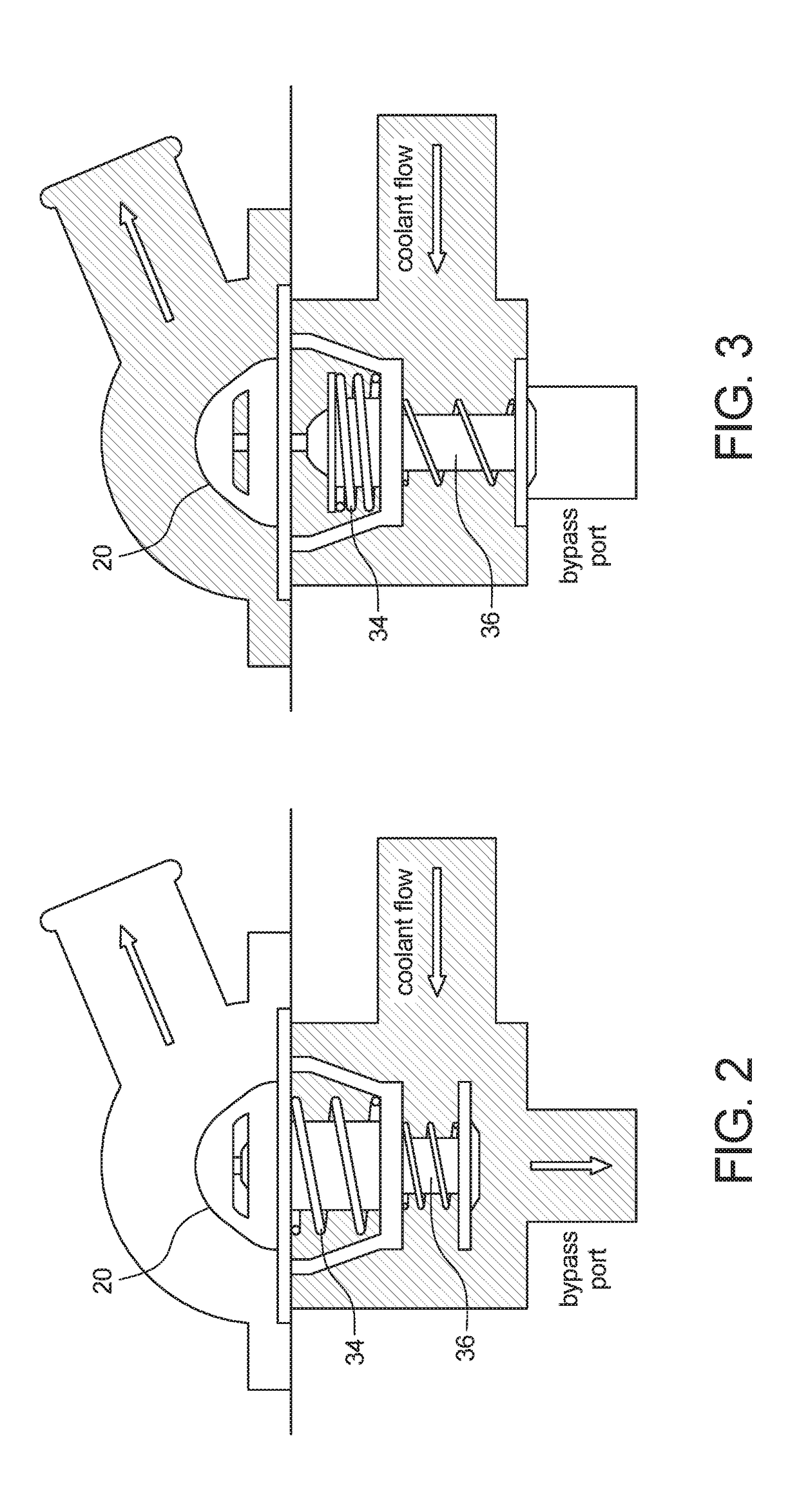
[0029]The engine E can operate at around 200 degrees F. At cold start up, the engine temperature is below this operating temperature and generally requires more fuel to run properly. Thus, as shown in FIG. 2, when the engine is cold the thermostat 20 blocks flow of the coolant to the radiator and opens the bypass circuit. In this mode the water pump 26 circulates coolant only inside the engine E. The coolant is prevented from flowing th...

case 1

[0044 illustrates a passing situation without use of the model (Zone 1). As shown in FIG. 9, when the actual ECT is greater than or equal to the second predetermined temperature (Temp ii) the system 10 using the passing zone without the model. In this passing zone, the passing index is incremented by a predetermined number stepα (e.g., 5), regardless of the estimation value from model. Once the passing timer crosses a threshold, a pass can be reported and numerator is incremented by 1.

case 2

[0045 illustrates a passing situation with the model (Zone 2). As shown in FIG. 9, when the actual ECT is less than the second predetermined temperature (Temp ii), but greater than the first predetermined temperature, the system 10 utilizes the passing zone with the model. That is, the controller 14 compares the actual ECT with a predetermined model, based on any suitable engine variables and / or factors. In this embodiment, the passing index will increment by a predetermined number stem (e.g., 1). In this embodiment, the passing index can hold its value if the actual ECT is less than the model and the passing index is non-zero.


PUM

PropertyMeasurementUnit
temperatureaaaaaaaaaa
temperaturesaaaaaaaaaa
speedaaaaaaaaaa

Abstract

A thermostat monitoring method includes measuring an engine coolant temperature with an engine coolant temperature sensor a predetermined amount of time after engine startup, comparing, with a controller, the engine coolant temperature to determine whether the engine coolant temperature has met a predetermined threshold, when the engine coolant temperature has met the predetermined threshold, measuring a plurality of engine coolant temperatures with the engine coolant temperature sensor, comparing with the controller each of the plurality of engine coolant temperatures with a corresponding predetermined temperature model, and increasing a passing index with the controller for each of the plurality of engine coolant temperatures that is greater than the corresponding predetermined temperature model or reducing the passing index for each of the plurality of engine coolant temperatures that is less than the corresponding predetermined temperature model.

Description

BACKGROUNDField of the Invention[0001]The present invention generally relates to a thermostat monitoring system and method. More specifically, the present invention relates to a thermostat monitoring system and method that detects a thermostat malfunction or failure.Background Information[0002]Generally conventional engines include a thermostat to maintain the engine near an optimum operating temperature by regulating the flow of coolant to an air-cooled radiator. Various thermostat diagnostic apparatuses have been proposed for diagnosing if a vehicle's thermostat of a cooling system is malfunctioning. Some conventional thermostat diagnosis system use a model to estimate ECT during the cold start of the engine.SUMMARY[0003]Current regulations require accuracy in the monitoring and diagnosing of thermostat operations after engine warms up. To meet the new regulation requirements, a new engine coolant temperature estimation model used to compare with measured temperatures is needed. I...

Claims


Application Information

Patent Timeline
Patent Type & Authority Applications(United States)
IPC IPC(8): G01K15/00F01P11/16G01K13/02
CPCG01K15/007F01P11/16G01K2013/026F01P2025/62F01P2025/66G01K13/02G01K2205/00G01K13/026
Inventor GUO, YICHAODANQUAH, EUGENELU, WEIKOWALKOWSKI, JANEANCRARY, BRENT
Owner NISSAN MOTOR CO LTD
Why Eureka
Try Eureka