Valve

a valve and valve body technology, applied in the field of valves, can solve the problems of loss of pressure, reducing the phase rate performance of the cam phasing system, and bulky check valves, and achieve the effect of greater fluid flow

Active Publication Date: 2018-12-13
DELPHI INT OPERATIONS LUXEMBOURG S A R L
View PDF0 Cites 6 Cited by
  • Summary
  • Abstract
  • Description
  • Claims
  • Application Information

AI Technical Summary

Benefits of technology

[0025]In embodiments where the or each blocking element is elongate along a circumferential direction of the tubular shell, the valve opening may be elongate in the circumferential direction of the tubular shell. In this way the opening may have an oval-shaped cross section which allows a greater flow of fluid through the opening.
[0026]The spool may comprise a fluid inlet, in which case the control valve may comprise a further valve as described above provided between the internal chamber of the spool and the fluid inlet such that the interior surface of the blocking element is exposed to fluid in the internal chamber, and the exterior surface of the blocking element is exposed to fluid in the fluid inlet, so that the blocking element can be deflected towards the central axis in response to fluid pressure in the fluid inlet to allow fluid to flow from the fluid inlet into the internal chamber of the spool, and can be deflected away from the central axis to block the fluid inlet in response to fluid pressure in the internal chamber to guard against fluid flowing from the internal chamber into the fluid inlet. In this way, the valve can also be used to prevent back-flow of fluid into the engine.

Problems solved by technology

Oil in the OCV tends to become pressurised during use and high pressure oil could flow in a reverse direction back up the oil port into the engine, which would result in a loss of pressure, and hence diminishing the phase rate performance of the cam phasing system.
Check valves can be integrated into the OCV to prevent this reverse flow of oil; however, these check valves are also bulky, and add to the size and weight of the OCV.

Method used


Image

  • Valve
  • Valve
  • Valve

Examples


Embodiment Construction

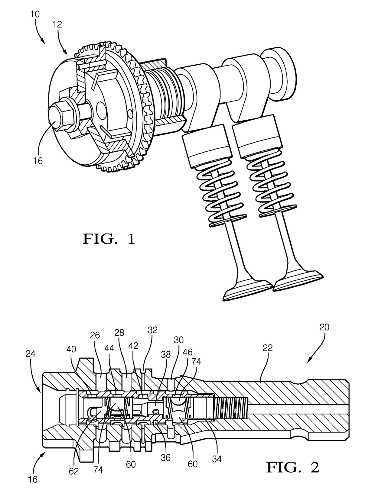
[0036]FIG. 1 shows a Cam phaser assembly 10. The cam phaser assembly 10 comprises a cam phaser 12 that drives a cam shaft 14. Inside the cam phaser 12 are two chambers: an advance chamber and a retard chamber (not visible). A bolt 16 is incorporated into the cam phaser assembly 10 at the axis of rotation of the cam shaft. An control valve in the form of an oil control vale (OCV) 20 is incorporated into the bolt 16 and controls a flow of fluid between the advance and retard chambers of the cam phaser 12 to rotate the cam phaser 12 in the advance or retard directions.

[0037]FIG. 2 shows the bolt 16 and the incorporated OCV 20. The OCV 20 comprises a housing 22, in this case defined by the bolt 16, having an internal cavity 24. Sets of radial openings 26, 28, 30, 32 define ports that open into the internal cavity 24. In this example, each set comprises three radial openings. An advance port 26 leads to the advance chamber of the cam phaser 12, and the retard port 28 leads to the retard ...


PUM


Abstract

A valve for restricting flow through an opening of a control valve in a vehicle engine includes a tubular shell having a central axis that extends between open ends of the shell. The shell also includes a base and a blocking element having an interior surface exposed to an internal space of the shell and an exterior surface exposed to an exterior space surrounding the shell. The blocking element is connected to the base by a deflectable connector such that the blocking element can be deflected towards the central axis in response to fluid pressure acting on the exterior surface, and away from the central axis in response to fluid pressure acting on the interior surface so as to selectively block the opening.

Description

CROSS REFERENCE TO RELATED APPLICATIONS[0001]This application is a national stage application under 35 USC 371 of PCT Application No. PCT / EP2016 / 064890 having an international filing date of Jun. 27, 2016, which is designated in the United States and which claimed the benefit of GB Patent Application No. 1512687.3 filed on Jul. 20, 2015, the entire disclosures of each are hereby incorporated by reference in their entirety.FIELD OF THE INVENTION[0002]The present disclosure relates to a valve for use in a control valve in a vehicle engine. The invention also relates to a control valve incorporating the valve.BACKGROUND OF THE INVENTION[0003]Cam phasers are used to control the angular relationship of the pulley / sprocket to the camshaft of an engine. A variable cam phaser (VCP) allows the phase relationship to change while the engine is running. Typically, a cam phaser is used to shift the intake cam on a dual overhead cam engine in order to broaden the torque curve of the engine, to in...

Claims


Application Information

Patent Timeline
Patent Type & Authority Applications(United States)
IPC IPC(8): F01L1/344F01L1/053
CPCF01L1/3442F01L1/053F01L2001/34433F01L2101/00F01L2103/00F01L2001/34483F01L2001/0537F01L2001/34426F01L2301/00F01L2303/00
Inventor LEBLAY, ARNAUDBOURNICHE, ERICBERHIN, RODRIGUE
Owner DELPHI INT OPERATIONS LUXEMBOURG S A R L
Why Eureka
Try Eureka