Apparatus for Improving Magnetic Resonance Imaging

a magnetic resonance imaging and apparatus technology, applied in the field of medical imaging, can solve the problems of affecting affecting the signal-to-noise ratio (snr) of the captured signals, and affecting so as to improve the signal-to-noise ratio of the received signals. , to achieve the effect of improving the operation of the mri machin

Active Publication Date: 2018-12-13
TRUSTEES OF BOSTON UNIV
View PDF1 Cites 5 Cited by
  • Summary
  • Abstract
  • Description
  • Claims
  • Application Information

AI Technical Summary

Benefits of technology

[0009]An illustrative embodiment provides an apparatus for improving operation of an MRI machine, the MRI machine characterized by a working frequency, by improving the signal-to-noise ratio of signals received by the MRI machine. The apparatus includes an array of unit cells, the array sized to be (or configured to be) disposed within a bore of the MRI machine along with a specimen in the bore, when the MRI machine is imaging the specimen. Each unit cell has a resonant frequency, and the array has a resonance frequency at or near the working frequency of the MRI machine (for example, in some embodiments the array has a resonance frequency with + / −5% (inclusive) of the working frequency of the MRI machine). The unit cells are configured such that they couple with one another (e.g., magnetically couple with one another), the array producing, in the signals measured by the MRI machine, a signal-to-noise ratio of at least 50. In some embodiments, the unit cells are low-dielectric constant resonators. In preferred embodiments, the unit cells are configured to amplify the magnetic field of the signal, but not amplify the electric field of the signal.

Problems solved by technology

A known limitation of MRI machines is the signal-to-noise ratio (SNR) of the captured signals.
Noise is generated by a variety of sources, including the circuitry of the MRI machine itself, and corrupts and obscures the signals emitted by the specimen.
Such approaches are less than ideal, however, there are limits to the amount of power that can be safely applied to some specimens, such as a living animal, and noise cannot be completely eliminated.

Method used


Image

  • Apparatus for Improving Magnetic Resonance Imaging
  • Apparatus for Improving Magnetic Resonance Imaging
  • Apparatus for Improving Magnetic Resonance Imaging

Examples


Embodiment Construction

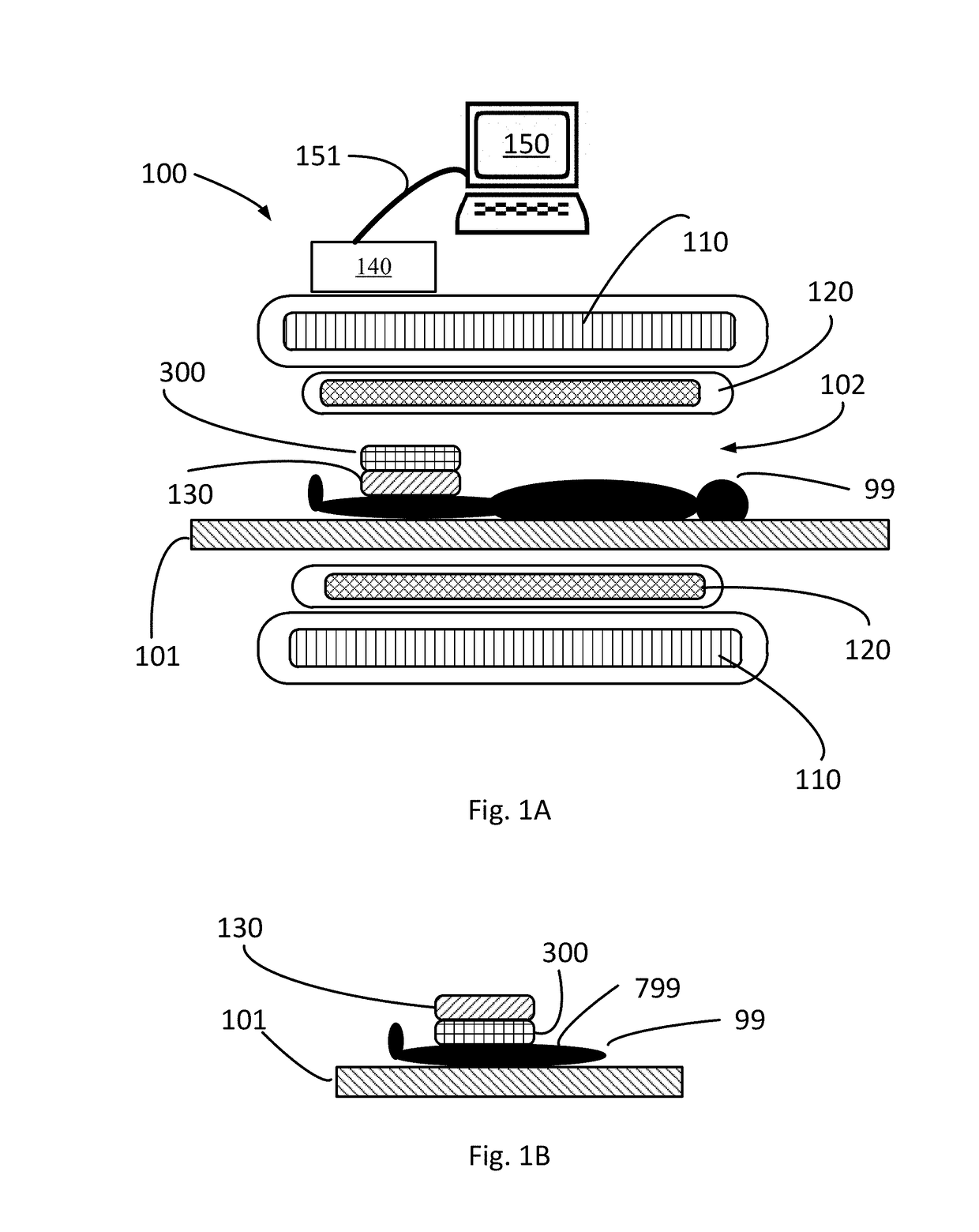
[0005]In accordance with illustrative embodiments, an apparatus includes a plurality of resonators, and operates to increase the signal-to-noise ratio of radiofrequency signals emitted by a patient and captured by an MRI machine.

[0006]In an illustrative embodiment, the apparatus includes an array of resonators (each resonator is a “unit cell”) configured to resonate at the working frequency. The array is configured to be disposed within the bore of an MRI machine, along with a specimen in the bore, when the MRI machine is imaging the specimen. In operation, the array increases the signal-to-noise ratio of the signals measured by the MRI machine.

[0007]In some embodiments, the apparatus has a resonance frequency different from the working frequency of the MRI machine. Indeed, in some embodiments the apparatus has a resonance frequency that can be tuned by changing the spacing between the resonators of the array.

[0008]In some embodiments, each resonator is a broadside-coupled split-rin...


PUM


Abstract

A passive apparatus including a plurality of resonators increases signal-to-noise ratio of radiofrequency signals emitted by a specimen and captured by an MRI machine. The apparatus increases the magnetic field component of radiofrequency energy during signal transmission from the MRI machine to the specimen, and/or reception of signals from the specimen to the MRI machine. Moreover, the apparatus enhances specimen safety by substantially avoiding unwanted generation of an electric field, or an increase in the electric field component of the RF energy. Use of the apparatus improves the images generated by the MRI machine, and/or reduces the time necessary for the MRI machine to capture the image.

Description

TECHNICAL FIELD[0001]This patent application claims priority from provisional U.S. patent application No. 62 / 516,376, filed Jun. 7, 2017, entitled, “Apparatus for Improving Magnetic Resonance Imaging,” and naming Xin Zhang, Stephan Anderson, Guangwu Duan, and Xiaoguang Zhao as inventors [practitioner's file 3273 / 119], the disclosure of which is incorporated herein, in its entirety, by reference.TECHNICAL FIELD[0002]The present invention relates to medical imaging, and more particularly to magnetic resonance imaging.BACKGROUND ART[0003]Magnetic resonance imaging (“MRI”) is a medical imaging technique that captures an image of a specimen's internal structures without the use of X-rays. An MRI machine applies a strong magnetic field and electromagnetic stimulus to the specimen, causing atoms of the specimen to emit electromagnetic signals in response. The MRI machine captures the electromagnetic signals emitted by the specimen and from those captured signals constructs the image.[0004]...

Claims


Application Information

Patent Timeline
Patent Type & Authority Applications(United States)
IPC IPC(8): G01R33/56A61B5/055G01R33/343G01R33/36
CPCG01R33/5608A61B5/055G01R33/343G01R33/3628G01R33/3415G01R33/3642
Inventor ZHANG, XINANDERSON, STEPHANDUAN, GUANGWUZHAO, XIAOGUANG
Owner TRUSTEES OF BOSTON UNIV
Why Eureka
Try Eureka