
Suspension board with circuits

a suspension board and circuit technology, applied in the field can solve the problems of reduced reliability of suspension boards with circuits, increased thermal hysteresis, and increased thermal damage, so as to achieve stable support, suppress the increase of thermal hysteresis, and maintain reliability

Inactive Publication Date: 2018-12-13
NITTO DENKO CORP
View PDF0 Cites 0 Cited by
  • Summary
  • Abstract
  • Description
  • Claims
  • Application Information

AI Technical Summary

Benefits of technology

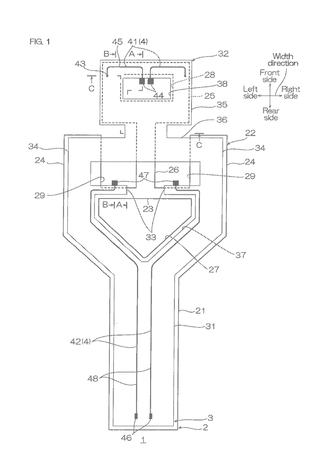
The present patent text describes a suspension board with circuits that has a pedestal formed across multiple wires. This helps to stably support a slider. However, the current design with multiple insulating layers has disadvantages such as increased thermal hysteresis and reduced reliability. The technical effect of this invention is to provide a suspension board with circuits with a lesser number of insulating layers, improved reliability, and increased flexibility for placement of the pedestal and wires.

Problems solved by technology

Then, formation of the insulating layer involves heating processes such as thermosetting, and therefore there are disadvantages such as the following: thermal hysteresis increases in the suspension board with circuits, thermal damages are amplified, and reliability of the suspension board with circuits is reduced.

Method used


Image

  • Suspension board with circuits
  • Suspension board with circuits
  • Suspension board with circuits

Examples


first embodiment

Modified Example of First Embodiment

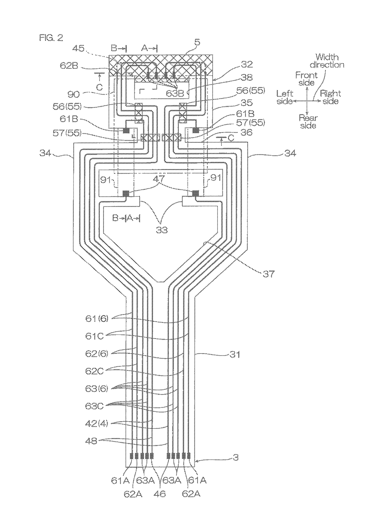
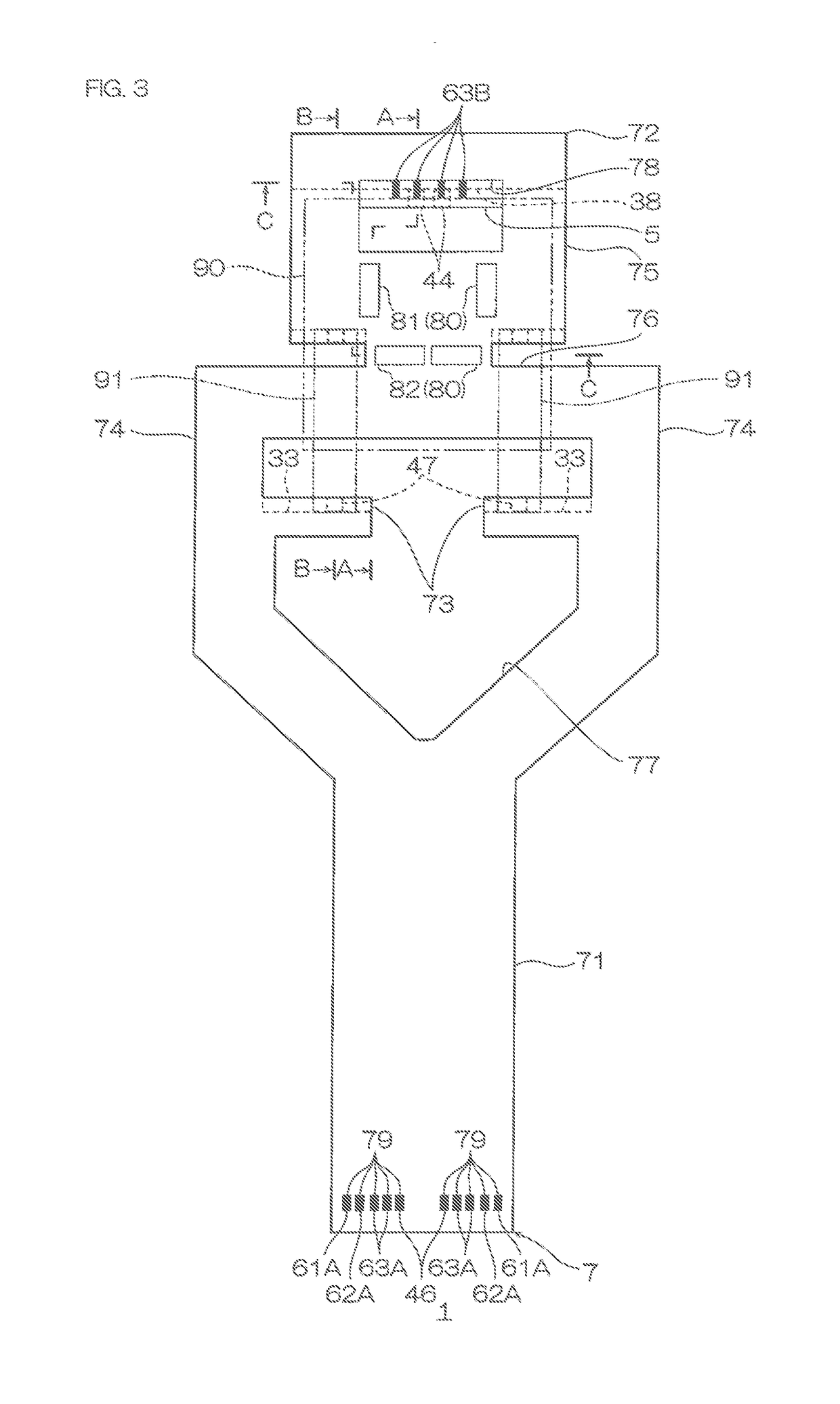
[0197]In the embodiment shown in FIG. 4, the plurality of wires (third power source terminal 61C, first rear power source wires 62C, and signal wires 63C) (wire not forming the pedestals 80) disposed in the rear side portion of the slider mounting region (for example, rear end portion of inner-insulating base layer 36) are formed as the second conductive pattern 6. That is, these wires are formed simultaneously with the plurality of wires (61C, 62C, 63C) forming the pedestals 80, but for example, as shown in FIG. 9, the plurality of wires (wire not forming the pedestals 80) disposed at the rear end portion of the inner-insulating base layer 36 can also be formed as the first conductive pattern 4.

[0198]That is, the first conductive pattern 4 further includes the first conductive pattern-third power source wire 161C, first conductive pattern-first rear power source wire 162C, and first conductive pattern-signal wire 163C.

[0199]In this embodiment, th...

second embodiment

Modified Example of Second Embodiment

[0239]In the embodiment shown in FIG. 12, the plurality of wires (third power source wire 61C, first power source wire 262C, and rear signal wire 263C)(wire not forming the pedestals 80) are disposed in the rear side portion of the slider mounting region (for example, rear end portion of the inner-insulating base layer 36) as the first conductive pattern. That is, these wires are formed simultaneously with the plurality of wires (61C, 262C, 263C) forming the pedestals 80, but for example, as shown in FIG. 14, the plurality of wires (wire not forming the pedestals 80) disposed at the rear end portion of the inner-insulating base layer 36 can also be formed as the second conductive pattern 6.

[0240]That is, the second conductive pattern 6 further includes the second conductive pattern-third power source wire 361C, second conductive pattern-first power source wire 362C, and second conductive pattern-rear signal wire 363C.

[0241]In this case, the termi...


PUM


Abstract

The suspension board with circuits can mount a slider and an electronic component, and includes a first insulating layer; a second insulating layer disposed on the first insulating layer; a third insulating layer disposed on the second insulating layer; a first conductive layer including an electronic component-connection terminal for electrically connecting with the electronic component, and a first wire disposed on the first insulating layer; a second conductive layer including a magnetic head-connection terminal for electrically connecting with a magnetic head provided in the slider, and a second wire, wherein at least a portion of the second wire is disposed on the second insulating layer. The suspension board with circuits has a pedestal supporting the slider. The pedestal includes the first insulating layer, second insulating layer, third insulating layer, and one of the first wire and second wire.

Description

CROSS REFERENCE TO RELATED APPLICATION[0001]The present application claims priority from Japanese Patent Application No. 2017-114508 filed on Jun. 9, 2017, the contents of which are hereby incorporated by reference into this application.BACKGROUND OF THE INVENTIONField of the Invention[0002]The present invention relates to a suspension board with circuits, particularly to a suspension board with circuits used for a hard disk drive.Description of Related Art[0003]Conventionally, for a suspension board with circuits, a suspension board with circuits having a slider with a magnetic head at a front end portion and mounted in a hard disk drive has been known. In such a suspension board with circuits, a pedestal for supporting and fixing the slider is provided (ref: Japanese Unexamined Patent Publication No. 2012-99204).[0004]The pedestal described in Japanese Unexamined Patent Publication No. 2012-99204 includes a first insulating base layer, a first conductive pattern formed thereon, an...

Claims


Application Information

Patent Timeline
IPC IPC(8): G11B5/48H05K1/18H05K3/46H05K3/00H05K3/34H05K3/40H05K1/11H05K3/18
CPCH05K3/4038H05K3/4007H05K3/188H05K3/3494H05K2201/09027H05K2201/10159H05K2201/10083H05K2201/10121H05K1/181G11B5/484H05K2203/0723H05K3/4644H05K3/0023H05K3/341H05K1/115G11B5/4833G11B5/4846G11B5/82G11B5/8404H05K1/056H05K2201/09045Y02P70/50
Inventor FUJIMURA, YOSHITOTANABE, HIROYUKISUGIMOTO, YUU
Owner NITTO DENKO CORP
Learn More