Wideband beam broadening for phased array antenna systems

a phased array antenna and wideband beam technology, applied in the field of phased array antennas, can solve the problems of spoiling techniques still not providing wide beams for wideband systems to solve these problems, and the main beam becomes too narrow for efficient implementation of some types of communication or radar applications, and the frame time becomes prohibitively long

Active Publication Date: 2018-12-13
THE BOEING CO
View PDF12 Cites 14 Cited by
  • Summary
  • Abstract
  • Description
  • Claims
  • Application Information

AI Technical Summary

Problems solved by technology

Unfortunately, as width of the main-beam decreases, the main-beam becomes too narrow for efficient implementation of some types of communication or radar applications that include, for example, radar search functions, null filing, floodlight mode illumination, and synthetic aperture radar (“SAR”).
As an example, in radar search functions, the main-beam may be so narrow that frame times becomes prohibitively long compared to the searched volume, in floodlight mode illumination applications where a missile is launched without a lock or the lock is lost during the missile time of flight, at endgame stage as the range is closing to zero where very high lateral accelerations might be used and update rates need to increase, and where the main-beam is too narrow compared with the target complex that is being illuminated to provide a wide beam to capture, re-capture, or lock on to the target of the missile.
Attempts to solve these problems have included utilizing beam spoiling techniques to shape and broaden the main-beams of known PAAs, however, the known beam spoiling techniques still do not provide wide enough beams for wideband systems to solve these problems.

Method used


Image

  • Wideband beam broadening for phased array antenna systems
  • Wideband beam broadening for phased array antenna systems
  • Wideband beam broadening for phased array antenna systems

Examples


Embodiment Construction

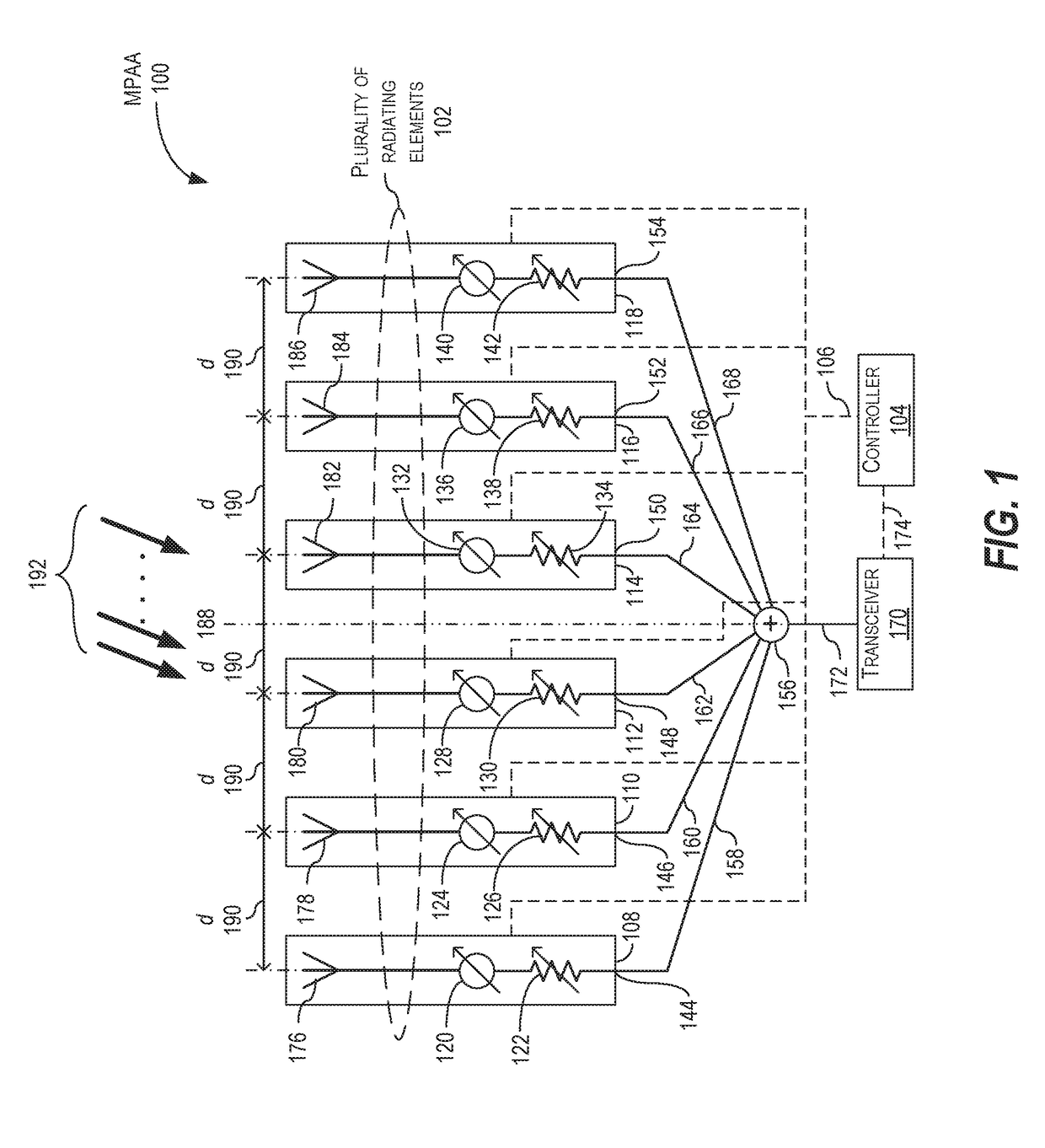
[0025]Disclosed is a multi-mode phased array antenna (“MPAA”). The MPAA has at least two modes of operation, where a first mode of operation produces a first main-beam and a second mode of operation produces a second beam. The MPAA includes a plurality of radiating elements arranged as an array of radiating elements and a controller in signal communication with the plurality of radiating elements. The controller is configured to excite the plurality of radiating elements to produce a first radiation pattern having the first main-beam in the first mode of operation and a second radiation pattern having the second beam in the second mode of operation. The second beam is wider than the first main-beam and the second radiation pattern is similar to a radiation pattern for a single radiating element of the plurality of radiating elements. The controller is also configured to switch between at least the first mode of operation and the second mode of operation.

[0026]In an example of operat...


PUM


Abstract

A multi-mode phased array antenna (“MPAA”) is disclosed. The MPAA has at least two modes of operation, where a first mode of operation produces a first main-beam and a second mode of operation produces a second beam. The MPAA includes a plurality of radiating elements arranged as an array of radiating elements and a controller in signal communication with the plurality of radiating elements. The controller is configured to excite the plurality of radiating elements to produce a first radiation pattern having the first main-beam in the first mode of operation and a second radiation pattern having the second beam in the second mode of operation. The second beam is wider than the first main-beam and the second radiation pattern is similar to a radiation pattern for a single radiating element of the plurality of radiating elements. The controller also switches between the first mode and second mode of operation.

Description

BACKGROUND1. Field[0001]The present disclosure is related to antennas systems, and in particular, to phased array antennas.2. Related Art[0002]At present, the utilization of phased array antennas (“PAAs” also known as “phased arrays,”“array antennas,”“electronically scanned array antennas,” or simply, “an array”) for modern communication and radar systems have become more common. In general, a PAA includes a large plurality of transmit or radiating (“transmit / receive” or “T / R”) elements where the T / R elements are such designed to result in deliberate electrical phase, amplitude and temporal relationships between each other. The PAA produces a far-field radiation pattern having beams that are formed by controlling the spectrum, timing, amplitude and phase of the signal emitted from each T / R element so as to provide constructive superposition or destructive interference of the total number of emitted signals from the plurality of T / R elements. In general, the interactions of the total...

Claims


Application Information

Patent Timeline
Patent Type & Authority Applications(United States)
IPC IPC(8): H01Q3/36H01Q21/22H01Q21/00
CPCH01Q3/36H01Q21/22H01Q21/0025G01S13/90G01S2013/0263H01Q21/061H01Q21/065H01Q21/08H01Q25/04H01Q3/26H01Q21/06H01Q25/002H01Q3/24
Inventor SHAPOURY, ALIREZA
Owner THE BOEING CO
Why Eureka
Try Eureka