Methods and Apparatus for Liquid Crystal Photoalignment

a liquid crystal and photoalignment technology, applied in the direction of liquid crystal compositions, chemistry apparatus and processes, instruments, etc., can solve the problem of not being able to apply reactive mesogen, and achieve the effect of stabilizing azo dye materials

Active Publication Date: 2018-12-20
KENT STATE UNIV +1
View PDF0 Cites 52 Cited by
  • Summary
  • Abstract
  • Description
  • Claims
  • Application Information

AI Technical Summary

Benefits of technology

[0011]The inventors have recognized that materials called reactive mesogens can be used to address the stability issues that plague conventional photoalignment layers. These materials can be applied as monomers and subsequently exposed to UV light to become polymers. Further, in their monomeric state, reactive mesogens can exist in the liquid crystalline state of matter, but then, after alignment by or to a photoalignment layer, can be polymerized to lock-in their order. Reactive mesogens have been applied by spin coating and have been shown to be effective in stabilizing azo dye materials to thermal stress. They have also been applied as an additive to liquid crystals and shown to be effect in stabilizing against electro-optic stress.

Problems solved by technology

The inventors have also recognized that spin coating reactive mesogen is not applicable to preformed cavity photonic devices and that using reactive mesogen to stabilize liquid crystals against electro-optic stress does not necessarily apply to azo dye materials or the stability of alignment under optical stress.

Method used


Image

  • Methods and Apparatus for Liquid Crystal Photoalignment
  • Methods and Apparatus for Liquid Crystal Photoalignment
  • Methods and Apparatus for Liquid Crystal Photoalignment

Examples


Embodiment Construction

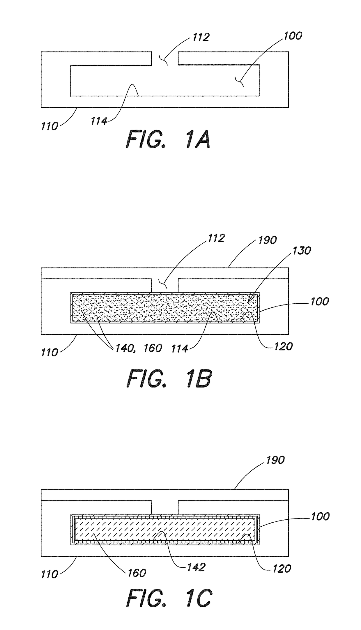
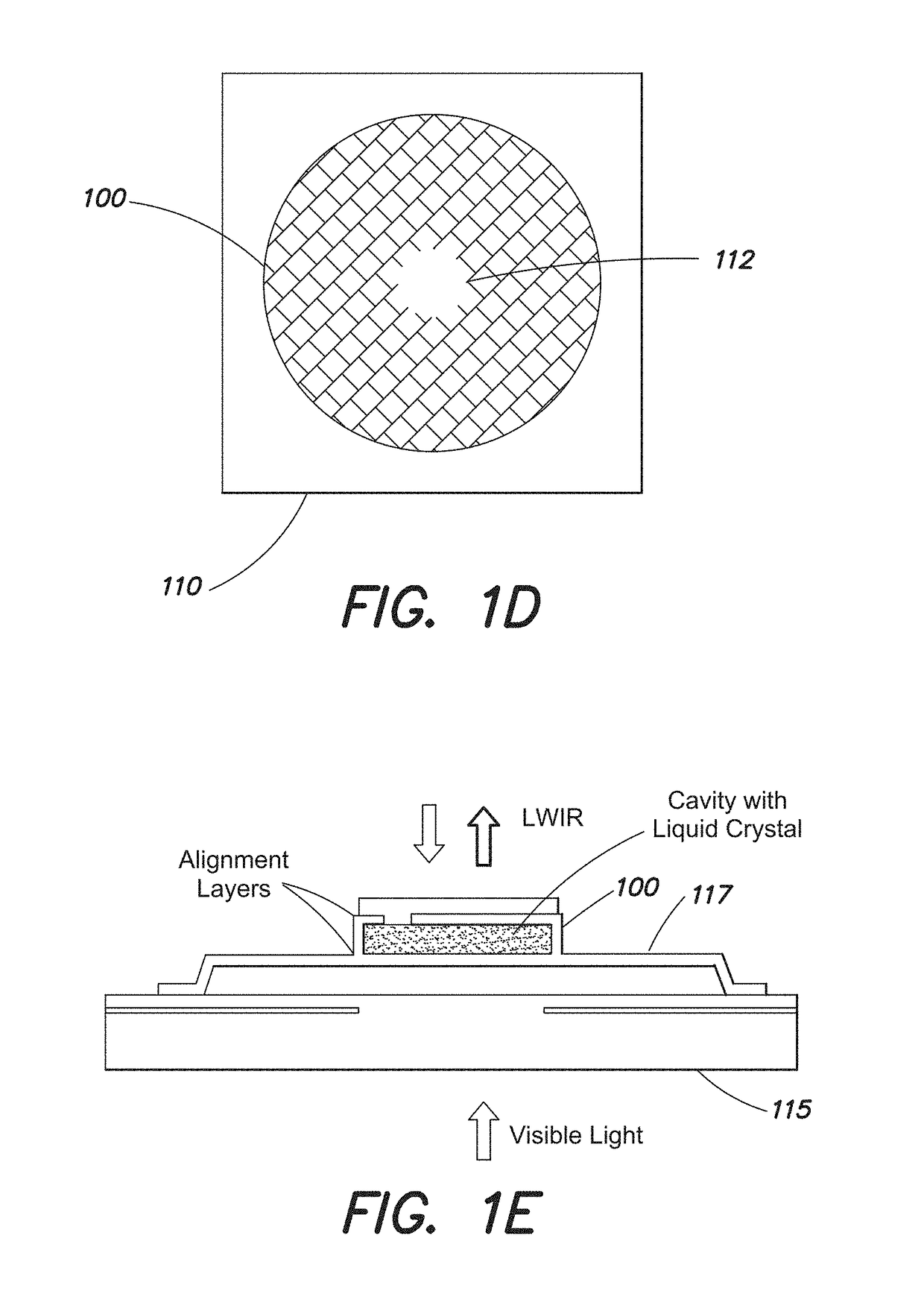
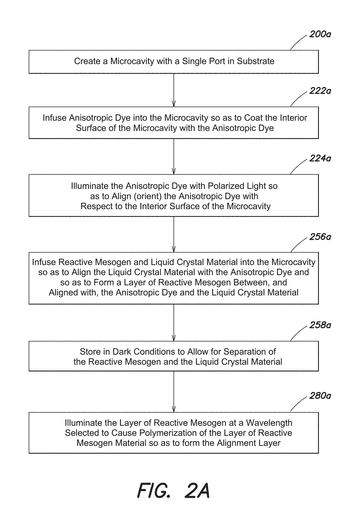
[0056]As discussed above, conventional photoalignment involves forming a layer of photo-alignable material, such as a dichroic dye (a dye that absorbs light anisotropically, such as Brilliant yellow or another azo dye), on the substrate surface. A thin coating of the azo dye is placed on the glass or electrode surface, and then blue polarized light is shined upon it. The polarized light aligns the azo dye molecules, which tend to be oblong, perpendicular to the polarization in a semi-permanent position. Unfortunately, azo dye layers are not stable enough for most applications as they tend to degrade when exposed to visible light.

[0057]Forming a layer of polymerized reactive mesogen (RM) or another suitable material over the azo dye layer effectively increases the photostability of the azo dye layer to create a more stable alignment layer. This material (e.g., the RM) forms a polymerized layer which, when polymerized, enforces the existing liquid crystalline alignment rather than dis...


PUM

PropertyMeasurementUnit
weight ratioaaaaaaaaaa
thicknessaaaaaaaaaa
thicknessaaaaaaaaaa

Abstract

Liquid crystal photonic devices and microcavities filled with liquid crystal materials are becoming increasingly popular. These devices often present a challenge when it comes to creating a robust alignment layer in pre-assembled cells. Previous research on photo-definable alignment layers has shown that they have limited stability, particularly against subsequent light exposure. A method of infusing a dye into a microcavity to produce an effective photo-definable alignment layer is described, along with a method of utilizing a pre-polymer infused into the microcavity mixed with the liquid crystal to provide photostability. In this method, the polymer layer, formed under optical irradiation of liquid crystal cells, is effectively localized to a thin region near the substrate surface and thus provides a significant improvement in the photostability of the liquid crystal alignment. This versatile alignment layer method, which can be used in microcavities to displays, offers significant promise for new photonics applications.

Description

CROSS-REFERENCE TO RELATED APPLICATION(S)[0001]This application is a divisional of U.S. application Ser. No. 14 / 845,924, entitled “Methods and Apparatus for Liquid Crystal Photoalignment” and filed on Sep. 4, 2015, which in turn claims the priority benefit under 35 U.S.C. § 119(e) of U.S. Application No. 62 / 046,706, entitled “Methods and Apparatus for Liquid Crystal Photoalignment” and filed on Sep. 5, 2014. Each of these applications is hereby incorporated by reference herein.GOVERNMENT SUPPORT[0002]This invention was made with government support under Contract No. FA8721-05-C-0002 awarded by the U.S. Air Force. The government has certain rights in the invention.BACKGROUND[0003]Liquid crystals (LCs) are materials that flow like liquid with crystalline solid-like ordered molecules that align and orient along a particular direction in the presence (or absence) of an electric field. These materials are widely used to manipulate the polarization and transmission of light, including in ...

Claims


Application Information

Patent Timeline
Patent Type & Authority Applications(United States)
IPC IPC(8): G02F1/1337G02F1/1333C09K19/56
CPCG02F2001/133726C09K19/56G02F1/133377G02F2202/043G02F1/133711G02F1/133788G02F1/133726
Inventor FINNEMEYER, VALERIE A.REICH, ROBERT K.CLARK, HARRY R.BOZLER, CARL O.BERRY, SHAUN R.BOS, PHILIP J.BRYANT, DOUGLAS R.
Owner KENT STATE UNIV
Why Eureka
Try Eureka