Monitoring control system, monitoring control device, and monitoring control method

a monitoring control system and control device technology, applied in the field of remote monitoring control technique, can solve the problem of not being able to shorten the moving time, and achieve the effect of reducing the amount of surrounding image data

Active Publication Date: 2018-12-20
HITACHI LTD
View PDF0 Cites 10 Cited by
  • Summary
  • Abstract
  • Description
  • Claims
  • Application Information

AI Technical Summary

Benefits of technology

[0005]Japanese Patent Application Publication No. 2014-071777 discloses a technique of performing MPEG (Moving Picture Experts Group) compression on surrounding images using a key frame and a difference fr...

Problems solved by technology

However, it is not possi...

Method used


Image

  • Monitoring control system, monitoring control device, and monitoring control method
  • Monitoring control system, monitoring control device, and monitoring control method
  • Monitoring control system, monitoring control device, and monitoring control method

Examples


embodiment 1

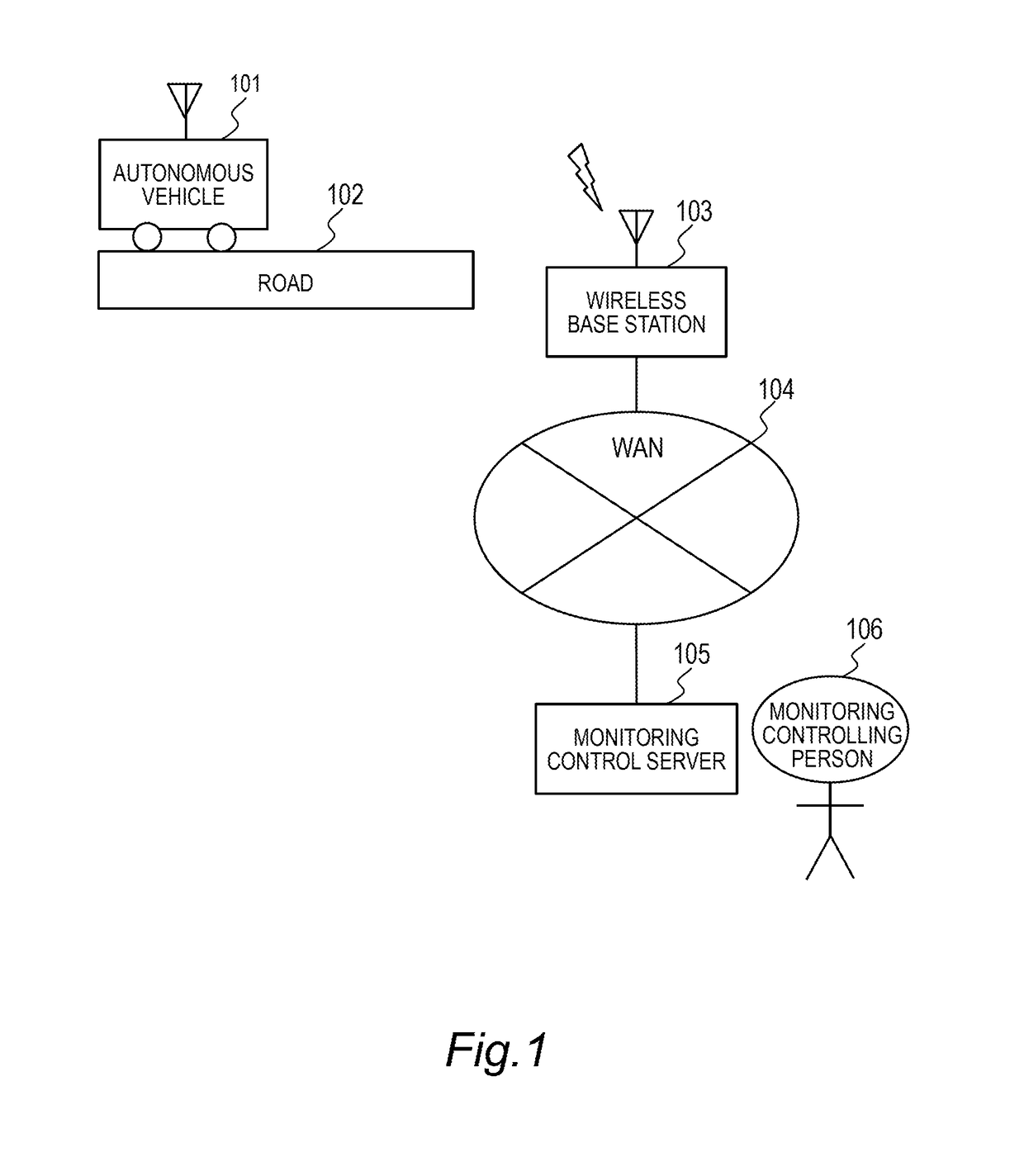
[0045]FIG. 1 is an explanatory diagram illustrating a configuration of an autonomous vehicle monitoring control system according to Embodiment 1 of the present invention.

[0046]The autonomous vehicle monitoring control system includes an autonomous vehicle 101, a road 102, a radio base station 103, a WAN 104, a monitoring control server 105, and a monitoring controlling person 106. FIG. 1 illustrates an example only and respective elements in the drawings may be provided plurally. For example, a plurality of autonomous vehicles 101 may be present in a certain autonomous vehicle monitoring control system. For example, a plurality of monitoring control servers 105 may be present in a certain autonomous vehicle monitoring control system. The autonomous vehicle 101 is an automobile travelling on the road 102. The autonomous vehicle 101 travels by automated driving or remote control. The autonomous vehicle 101 connects to the monitoring control server 105 via a radio base station 103 and ...

embodiment 21

[0122]Embodiment 2 of the present invention will be described with reference FIGS. 17 to 19. Since respective units of a system of Embodiment 2 have the same functions as respective units of Embodiment 1 illustrated in FIGS. 1 to 16, denoted by the same reference numerals as those of Embodiment 2 except for the difference to be described later, the description thereof will be omitted.

[0123]In the present embodiment, the configuration of the monitoring control server 105 is different from that of Embodiment 1.

[0124]FIG. 17 is a block diagram illustrating a configuration of the monitoring control server 105 according to Embodiment 2 of the present invention.

[0125]Among constituent elements in FIG. 17, the same portions as those illustrated in FIG. 8 will be denoted by the same reference numerals as those of FIG. 8, and the description thereof will be omitted. The monitoring control server 105 in FIG. 17 has monitoring control server software 801. The monitoring control server software...

embodiment 3

[0133]Embodiment 3 according to the present invention will be described with reference to FIGS. 20 to 22. Since respective units of a system of Embodiment 3 have the same functions as respective units of Embodiments 1 and 2 illustrated in FIGS. 1 to 19, denoted by the same reference numerals as those of Embodiments 1 and 2 except for the difference to be described later, the description thereof will be omitted.

[0134]In the present embodiment, the configuration of the monitoring control server 105 is different from that of Embodiment 1.

[0135]FIG. 20 is a block diagram illustrating a configuration of the monitoring control server 105 according to Embodiment 3 of the present invention.

[0136]Among constituent elements in FIG. 20, the same portions as those illustrated in FIG. 8 will be denoted by the same reference numerals as those of FIG. 8, and the description thereof will be omitted. The monitoring control server 105 in FIG. 20 has monitoring control server software 801. The monitor...


PUM


Abstract

A monitoring control system includes a mobile object and a server device that communicates with the mobile object. The mobile object includes: a first communication unit; a camera; an encoding unit that generates image data from the image captured by the camera; a transmitting unit that transmits the image data; and a movement control unit that controls movement of the mobile object according to a control signal received from the server device via the first communication unit, and the server device includes: a second communication unit that communicates with the mobile object; and an emergency control signal transmitting unit that transmits an emergency control signal to the mobile object via the second communication unit when at least a part of a key frame among the image data transmitted from the mobile object is not received within a predetermined period.

Description

CLAIM OF PRIORITY[0001]The present application claims priority from Japanese patent application JP2017-117581 filed on Jun. 15, 2017, the content of which is hereby incorporated by reference into this application.BACKGROUND OF THE INVENTION[0002]The present invention relates to a remote monitoring control technique for autonomous mobile objects.[0003]In recent years, automated driving techniques have been developed to provide inexpensive and safe moving means. In order to realize completely automated driverless driving, it is necessary to cope with imperfection in recognition, determination, and control. In order to put imperfect autonomous vehicles into practical use (launching) at an early stage, a method of guaranteeing safety by monitoring and controlling automated driving vehicles from a remote center has been considered. For example, a use case in which, in order to determine whether determination and control of automated driving is appropriate in a place where it is difficult...

Claims


Application Information

Patent Timeline
IPC IPC(8): G05D1/00H04N17/00H04L12/26H04N7/18G05D1/02
CPCG05D1/0055H04N17/00H04L43/0829H04N7/18G05D1/0088G05D1/0022G05D1/0231G05D1/0257G05D1/0278G05D2201/0213B60Q11/00H04L67/025H04L67/12H04N7/183G05D1/0027G05D1/0038G07C5/008G07C5/0866
Inventor YUNOKI, SHOJIENDO, HIDEKIKUBO, HIROYUKI
Owner HITACHI LTD
Why Eureka
Try Eureka