Supercharge Your Innovation With Domain-Expert AI Agents!

Dual-Capacitors-Based AC Line Frequency Low Voltage DC Power Supply Circuit

Inactive Publication Date: 2018-12-20
MOSWAY SEMICON
View PDF2 Cites 1 Cited by
  • Summary
  • Abstract
  • Description
  • Claims
  • Application Information

AI Technical Summary

Benefits of technology

This patent describes a circuit that uses two high-voltage capacitors and a rectifying bridge to create a balanced load on the AC line. The circuit also includes a device to limit the voltage at the intermediate (low-voltage) capacitor and a regulator to provide a stable output voltage. The main technical effect of this circuit is a more balanced and efficient load on the AC line compared to previous methods.

Problems solved by technology

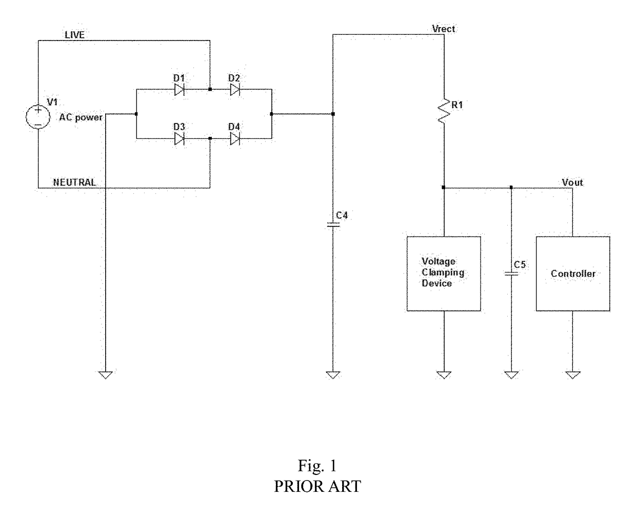
However, the circuit suffers from a number of drawbacks.
There is a large power loss in the resistor R1.
The resistor and voltage clamping device also exhibit low efficiency, poor thermal performance regarding power loss handling, and poor line and load regulation.
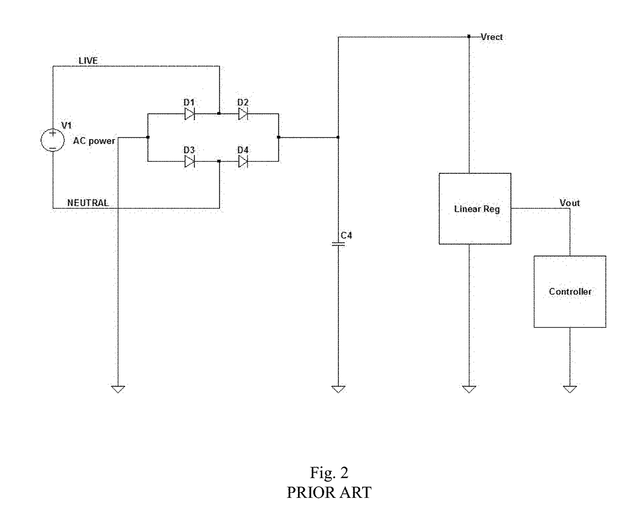
However, the HV circuit suffers from similar disadvantages to the resistor and voltage clamping device depicted in FIG. 1.
Specifically, the HV input linear regulator circuit suffers from high power loss in the series pass transistor, poor thermal performance, and needs a high voltage device as the series pass transistor.
This increases the cost of implementation.
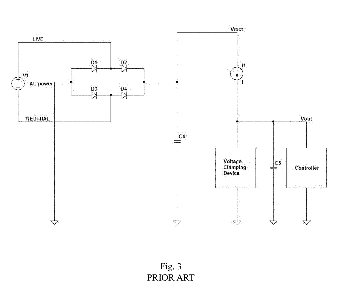
The inherent V-I loss on the current source itself is also still significant.
This circuit is undesirable because the current source must be operating at high voltage and the circuit itself is more complex.
The transformer required to attain the appropriate DC voltage is expensive and there is poor EMI performance.
However, the power loss overhead for the SMPS is very high if it is supposed to deliver only 10 mA 5 V to the load.
This results in a low efficiency circuit with poor EMI performance and there is audio noise as well.
The circuit also results in relatively low power loss.
It may cause breakdown to the device attached to Vrect line (e.g. HV capacitor, MOS switching device, etc.).
As there is only a small ripple on V(neutral) relative to GND, it is not sufficient to pump up the voltage at VC.
Hence, the circuit cannot operate properly under the light load condition.
This is mainly caused by the imbalance condition of the main rectifying bridge on the LIVE or NEUTRAL lines.
However, at light load condition, the ripple may not be high enough for the AC charge-pump action.
Otherwise, VC will not reach the desirable voltage level.
As a result, some minimum power is dissipated in R1, so it will reduce the overall efficiency.

Method used


Image

  • Dual-Capacitors-Based AC Line Frequency Low Voltage DC Power Supply Circuit
  • Dual-Capacitors-Based AC Line Frequency Low Voltage DC Power Supply Circuit
  • Dual-Capacitors-Based AC Line Frequency Low Voltage DC Power Supply Circuit

Examples


Embodiment Construction

[0038]With reference to the drawings wherein like numerals represent like parts throughout the figures, is a schematic circuit diagram for an embodiment of the disclosed dual-capacitor based AC line frequency low voltage DC power supply circuit is designated by the numeral 100 in FIG. 8.

[0039]The AC line voltage charges the intermediate low-voltage capacitor 102 via two high-voltage capacitors 104, 106. The two high-voltage capacitors 104, 106 are charged through the full wave rectifying bridge 110. The inrush current is limited by two resistors 120, 122, each mounted in series with a high-voltage capacitor 104, 106. The charging and discharging of current of the high-voltage capacitors 104, 106 is shown in FIG. 9A.

[0040]The dual high-voltage capacitors 104, 106 ensure a balanced load on the AC line at each AC voltage cycle. As a result, there will be no imbalanced peak voltages at Vrect that could otherwise go up to a much higher peak. Therefore, the maximum voltage at Vrect is kep...


PUM


Abstract

A supply circuit includes a rectifying bridge arranged in series between two high voltage capacitors. An AC line provides an intermediate voltage to a low voltage capacitor through the two high voltage capacitors. A plurality of resistors mounted in series with the two high voltage capacitors. A voltage clamping device limits the intermediate voltage at the low voltage capacitor and a linear series regulator provides an output DC voltage.

Description

BACKGROUND OF THE INVENTION[0001]The present invention relates to low voltage DC power supply circuits. The invention more particularly, although not exclusively, relates to dual-capacitor-based AC line frequency supply circuits for low voltage DC power.[0002]Prior art low power off-line AC-DC power supplies are shown in FIGS. 1-7. FIG. 1 shows a low voltage DC that is obtained by a resistor and voltage clamping device. A circuit using a typical implementation of a linear regulator, such as this method, is simple in design and low cost. However, the circuit suffers from a number of drawbacks. There is a large power loss in the resistor R1. A typical loss is 220V×15 mA=3.3 W; (where Iout=10 mA and IZener diode=5 mA). The resistor and voltage clamping device also exhibit low efficiency, poor thermal performance regarding power loss handling, and poor line and load regulation.[0003]FIG. 2 shows a high voltage (“HV”) input linear regulator.[0004]Compared to the circuit of FIG. 1, the HV...

Claims


Application Information

Patent Timeline
IPC IPC(8): H02M3/28H02M1/08H02M3/335G05F1/46
CPCH02M3/285G05F1/46H02M3/33592H02M1/08H02M7/02H02M7/06
Inventor TANG, CHI-KEUNGTSE, CHIU-SING CELEMENTWONG, NGAI WA
Owner MOSWAY SEMICON
Features
  • R&D
  • Intellectual Property
  • Life Sciences
  • Materials
  • Tech Scout
  • Unparalleled Data Quality
  • Higher Quality Content
  • 60% Fewer Hallucinations
Learn More