A configurable lighting system and method

a lighting system and configurable technology, applied in lighting devices, lighting sources, electrical devices, etc., can solve the problems of cost, complexity, and difficulty in installation and configuration of radio frequency control devices, and achieve the effect of cost and complexity of having to utilis

Active Publication Date: 2018-12-20
SIGNIFY HLDG BV
View PDF4 Cites 12 Cited by
  • Summary
  • Abstract
  • Description
  • Claims
  • Application Information

AI Technical Summary

Benefits of technology

[0080]iv. the cost and complexity of having to utilise relatively expensive radio frequency control devices such as mobile phones, tablets, computers and smart switches having touchscreen display interfaces as the primary control device on a daily basis, may be alleviated. Thus, for certain persons such as children or visitors to a premises who may not have own or have access to a mobile phone, they may now be able to use control the extended functional capabilities of the lighting unit simply by using the light switch or infrared remote control unit

Problems solved by technology

Whilst these types of control devices are suitable for operation of basic functionality such as switching the lighting units on or off, the basic design of these types of control devices means that they are limited in their ability to enable users to easily and conveniently access and control the full capabilities of more advanced lighting unit functions such as light dimming, white colour temperature tuning, and colour output adjustment.
However, whilst this integrated intelligence may be useful to certain users, it will not suit the preferences of all users and because this intelligent functionality is embedded in the lighting unit during manufacture, it is not possible for users to customise the intelligent functionality to respond in different ways.
However, these radio frequency control devices tend to be expensive and complicated to install and configure for use as the primary control device.
It is also not ideal for users to utilise these types of control devices as the primary control means as it is then inconvenient for the user to concurrently use the control device to perform other functions such as taking a telephone call, or when such a control device is being charged.
Moreover, if the radio frequency control device is used as the primary control device on a daily basis, it becomes more susceptible to wear and tear and is an expensive piece of equipment to have to repair if damaged.
Other solutions have sought to rely upon the use of overly-sophisticated and powerful wired smart controller devices such as smart switches, dimmers and RGB controllers that are based on the Digital Addressable Lighting Interface (DALI) international standard.
However, this solution involves replacement of the existing lighting system switches and lighting units by DALI-standard compatible control devices and DALI-standard compatible lighting units which is expensive, complicated and time-consuming to install into the existing physical infrastructure.
Whilst this may be suitable for certain enterprise-level users in a large-scale commercial environment, it may not be cost effective or practical for certain home users lacking a suitable budget and technical expertise to utilise.
Furthermore, for many users, it is not desirable for them to have to replace the existing control devices and lighting units that are already installed as these may have been carefully selected to match the existing decor.
Thus, if the user decides to replace the existing wired lighting infrastructure by installing new DALI-standard compatible control devices and lighting units, this is not only a relatively expensive and overly-sophisticated solution, but the user's choice of appearance of the new equipment is very limited and may not be aesthetically pleasing to the user's tastes and preferences.

Method used


Image

  • A configurable lighting system and method
  • A configurable lighting system and method
  • A configurable lighting system and method

Examples


Embodiment Construction

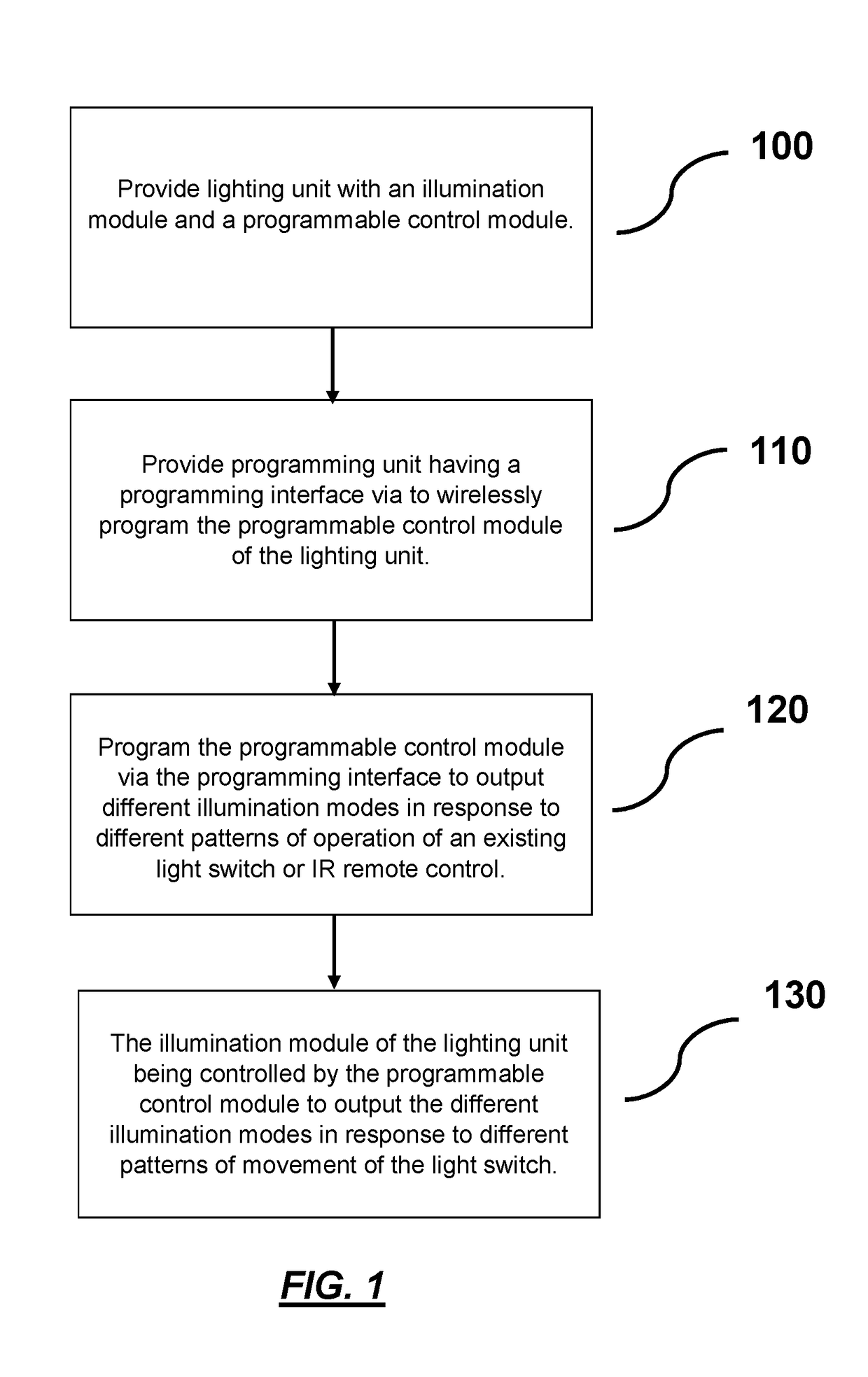
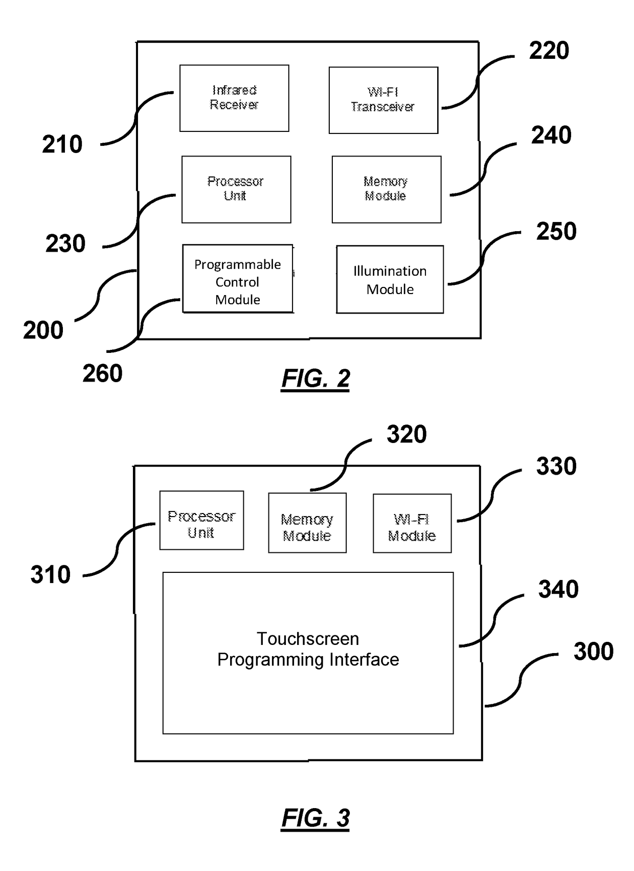
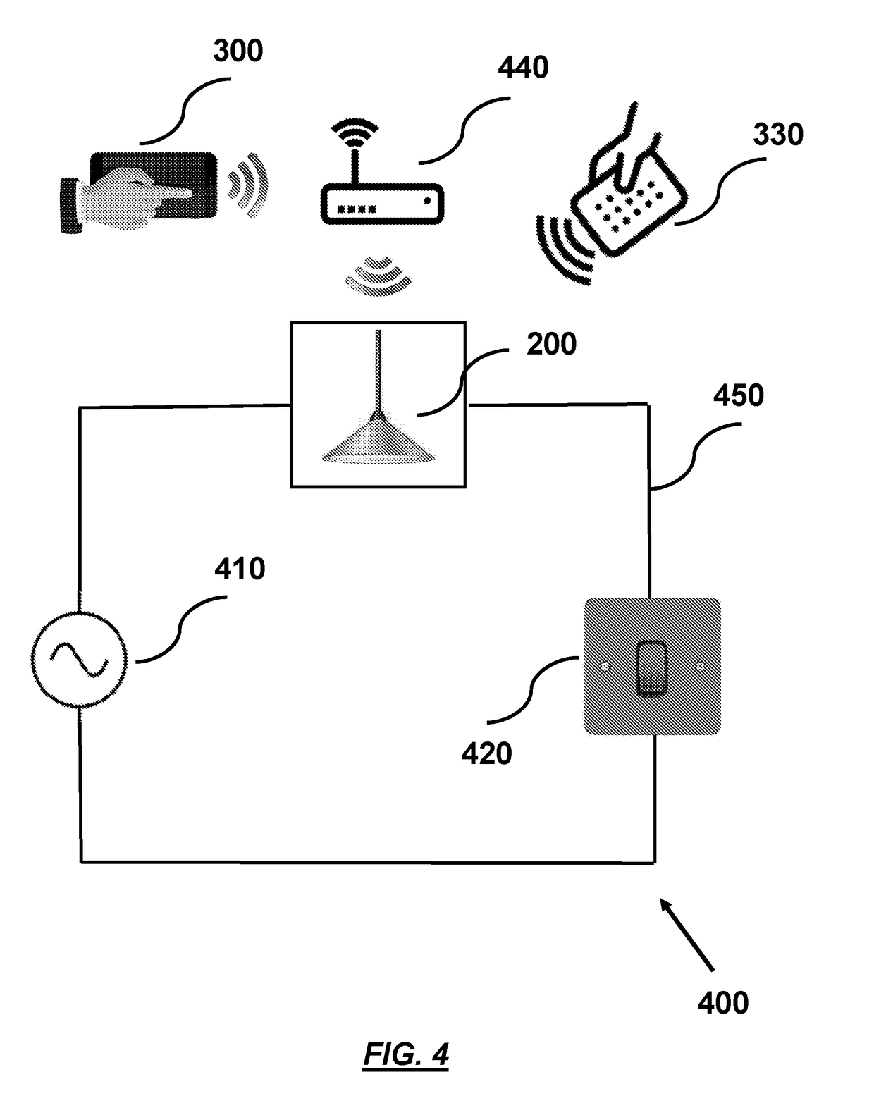
[0086]A configurable lighting system (400) is shown in FIGS. 1 to 4 in accordance with an embodiment of the present invention. The system comprises a lighting unit (200) which may for instance be implemented in the form of a lamp, luminaire or lightbulb installed in a household premises to provide extended lighting functionality such as brightness dimming, selectable colour scene modes, and white colour temperature adjustment. The lighting unit (200) is connected with a mains power supply (410) and a wall-mounted light switch (420) via existing standard electrical wiring and circuitry (450) installed in the framework of household premises. Typically, the light switch (420) may include for instance a toggle-type switch, a rocker-type switch, a push-button type switch, a dimmer-type switch, a pull-cord type switch, and an electronic-type switch each of which, in standard useage, is operable between first and second operational positions (or operational states) to enable switching of t...


PUM


Abstract

A configurable lighting system including a lighting unit having an illumination module and a programmable control module; a light switch configured for electrical communication with the lighting unit via an electrical circuit and being operable in a first and a second operational position such that the illumination module, in response to operation of the light switch in the first and the second operational positions, is able to output a first set of illumination modes; and, a programming unit configured for wireless communication with the programmable control module of the lighting unit via a wireless communication link wherein the programming unit includes a programming interface via which the programmable control module of the lighting unit is able to be programmed such that, in response to different patterns of movement of the light switch between the first and second operational positions, the illumination module is controlled by the programmable control module to output a second set of illumination modes having a greater number of illumination modes than that of the first set of illumination modes.

Description

TECHNICAL FIELD[0001]The present invention relates to systems and methods for controlling lighting units.BACKGROUND OF THE INVENTION[0002]Many lighting units such as lamps and luminaires are typically operated by control devices in the form of wall-mounted electrical switches or infrared remote controls. Whilst these types of control devices are suitable for operation of basic functionality such as switching the lighting units on or off, the basic design of these types of control devices means that they are limited in their ability to enable users to easily and conveniently access and control the full capabilities of more advanced lighting unit functions such as light dimming, white colour temperature tuning, and colour output adjustment.[0003]In seeking to address the deficiencies in existing control devices such as electric switches and infrared remote controls, certain advanced lighting units are provided with integrated intelligence whereby a pre-defined advanced lighting functi...

Claims


Application Information

Patent Timeline
Patent Type & Authority Applications(United States)
IPC IPC(8): H05B37/02
CPCH05B37/0272H05B37/029H05B37/0281H05B37/0227H05B47/105H05B47/17H05B47/195Y02B20/40H05B47/16H05B47/155
Inventor GAL, JEAN-PHILIPPE
Owner SIGNIFY HLDG BV
Why Eureka
Try Eureka