


Quick Research
Generate reliable direction feasibility study reports for your R&D in just a few steps.

Technical Q&A
Discover and master advanced knowledge NOW. Basics, ideas, possibilities, all at once.

Find Solutions
As an expert in R&D theories, this can generate solutions to your technical problems instantly.

Evaluate Feasibility
Analyze your overall solution with one click, know your potential R&D risks in advance.

Monitor Landscape
Get weekly tech updates, stay abreast of the latest tech innovations and key insights.
Footwear
a technology for shoes and soles, applied in the field of shoes, can solve the problems of unavoidably limited cushioning performance of soles, harmful influences on the human body, and thin soles, and achieve the effects of efficiently removing vibrations of specific frequencies, efficiently absorbing energy generated by landing impact of feet, and reducing the effect of friction
- Summary
- Abstract
- Description
- Claims
- Application Information
AI Technical Summary
Benefits of technology
Problems solved by technology
Method used
Image

Examples
first embodiment
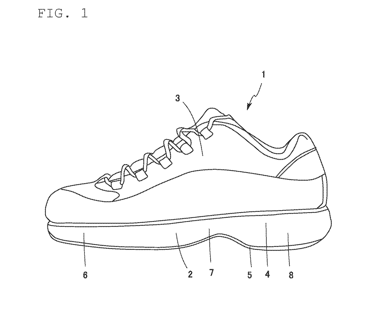
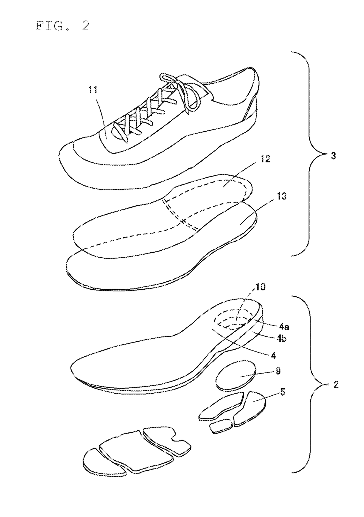
[0060]FIG. 1 shows an external structure of a sports shoe as a first embodiment of the footwear according to the present invention, whereas FIG. 2 is an exploded perspective view of the sports shoe in FIG. 1. A sports shoe 1 according to the present embodiment includes a sole (shoe sole) 2 and an upper (top part) 3 which is connected onto an upper side of the sole 2. While the sports shoe 1 is provided in a mutually symmetrical pair of a left and a right shoes (one shoe for the right foot and the other for the left), FIG. 1 and FIG. 2 show only one for the left foot.
[0061]In the present embodiment, the sole 2 has a multi-layer structure as shown in FIG. 2, including a midsole 4 and an outer sole 5. The sole 2 may be provided by a foamed or non-foamed body which is made of rubber, resin and so on as a suitable material.
[0062]The midsole 4 has a laminated structure of an upper midsole 4a and a lower midsole 4b. The laminated structure is utilized entirely in the present embodiment for...
second embodiment
[0104]FIG. 13 is an exploded perspective view as a schematic drawing which shows an arrangement of a sole portion of a sports shoe according to a second embodiment of the present invention. In the present embodiment, a sole 2 has a shank 26 disposed at the arch of the foot. The shank is a member used in a shoe sole to keep the shape of the arch of the foot, supports the arch region from below, and has a hardness to protect its arch shape from being collapsed by the user's weight. The shank may be made of a metal or a synthetic resin for example.
[0105]Behind the shank 26, a lower midsole 4b is provided only in a heel region 8. The lower midsole 4b is connected to an upper midsole 4a in lamination, and they form a midsole 4.
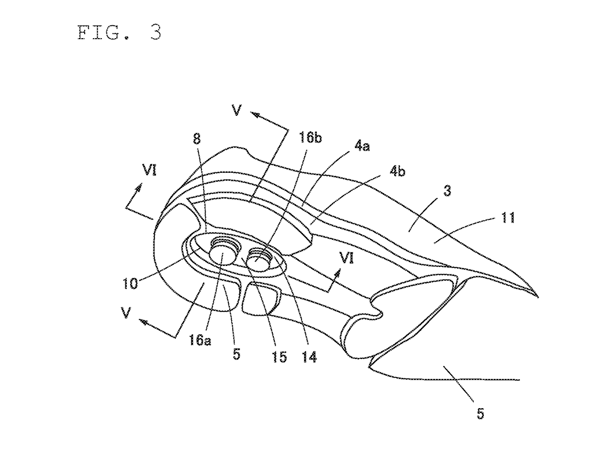
[0106]In the heel region 8 of the midsole 4, a housing space 10 is provided to house a vibration absorbing unit 14. The housing space 10 is a hole which opens in a bottom surface of the heel region 8 of the sole 2, and is shaped as a hollow in the midsole 4. Specif...
third embodiment
[0111]FIG. 14 includes two schematic drawings which show an arrangement of a sole portion of a sports shoe (for a left foot) according to a third embodiment of the present invention; FIG. 14(a) is a perspective view with a partial section, whereas FIG. 14 (b) is a side view. FIG. 15 is a side view which shows the sole portion in FIG. 14 under a load. In the present embodiment, a sole 2 has its midfoot region 7 as a place where a housing space 10 is provided to house a vibration absorbing unit 14. Also, a vibration absorbing unit 14 includes three support portions 15 which vibrate at different frequencies from each other. Also, a support portions 15 are supported at their ends in the width direction of the sole 2.
[0112]The housing space 10 provided in the sole 2 is positioned at the midfoot region 7 which includes the arch of the foot as above-mentioned. As will be described later, the dimension of the height of the housing space 10 may be selected accordingly with the dimension of t...
PUM
| Property | Measurement | Unit |
|---|---|---|
| mass | aaaaa | aaaaa |
| frequencies | aaaaa | aaaaa |
| frequencies | aaaaa | aaaaa |
Abstract
Description
Claims
Application Information
 - R&D Engineer
- R&D Manager
- IP Professional
- Industry Leading Data Capabilities
- Powerful AI technology
- Patent DNA Extraction
Browse by: Latest US Patents, China's latest patents, Technical Efficacy Thesaurus, Application Domain, Technology Topic, Popular Technical Reports.
© 2024 PatSnap. All rights reserved.Legal|Privacy policy|Modern Slavery Act Transparency Statement|Sitemap|About US| Contact US: help@patsnap.com