
Method and device for producing an object by using a 3D printing device

a 3d printing and object technology, applied in the direction of additive manufacturing with liquids, manufacturing tools, manufacturing processes, etc., can solve the problems of unsuitable moldings consisting of silicone elastomers, large crosslinking rate reduction, cloudiness,

Active Publication Date: 2018-12-27
WACKER CHEM GMBH
View PDF0 Cites 8 Cited by
  • Summary
  • Abstract
  • Description
  • Claims
  • Application Information

AI Technical Summary

Benefits of technology

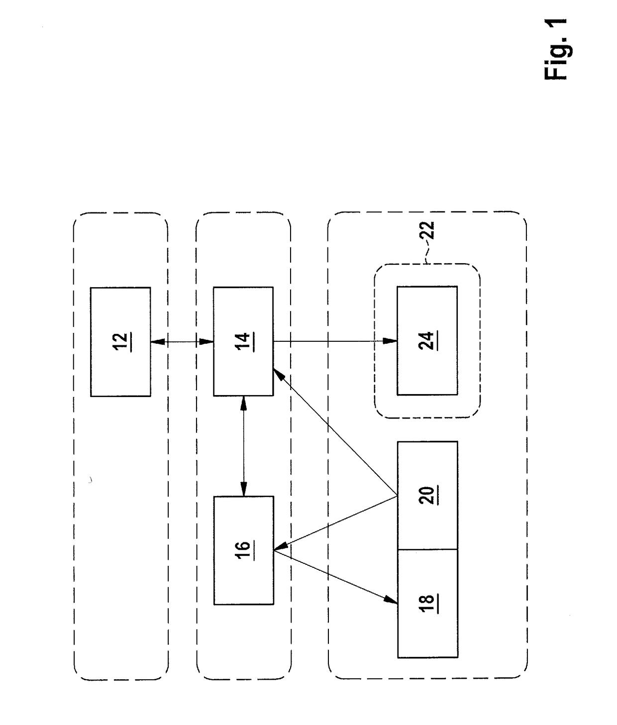
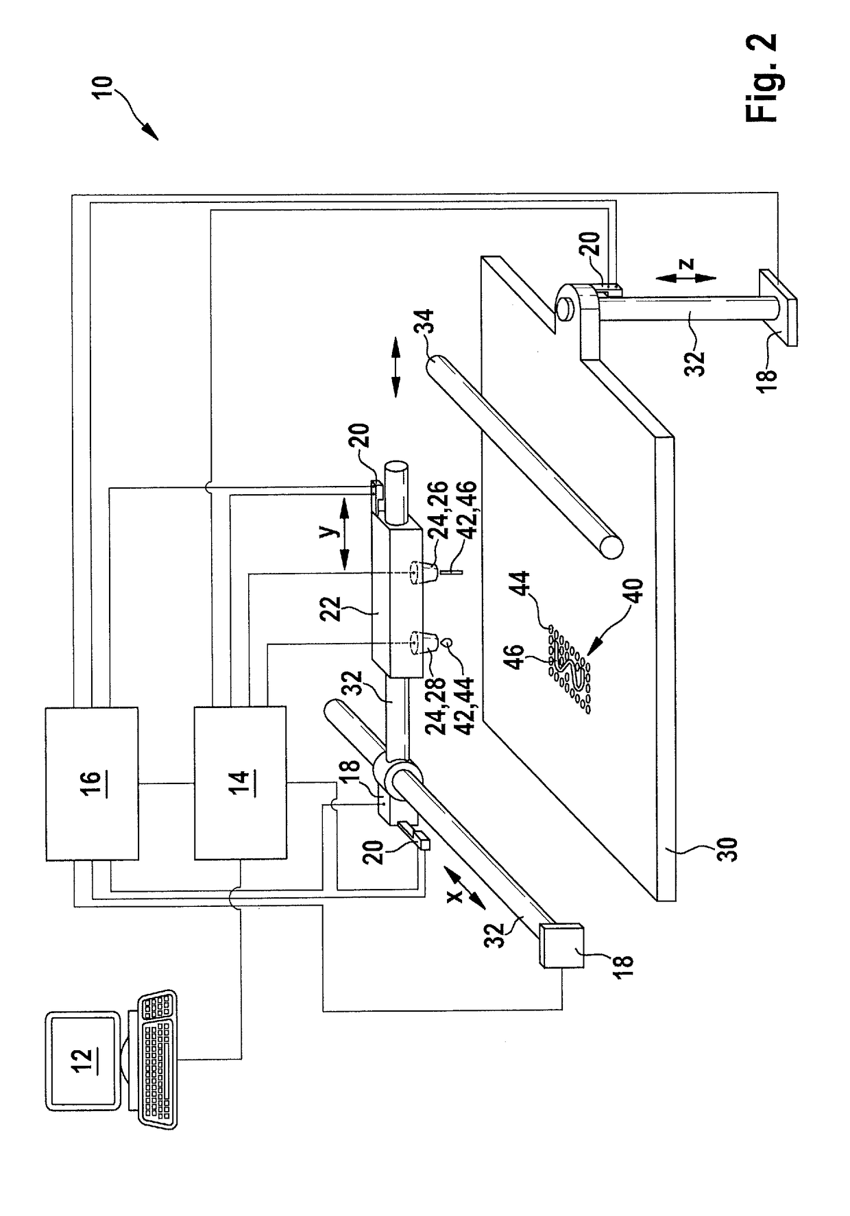
The 3D printing device has a cleaning station that can automatically clean the discharge device of the printhead while the device is in use. This means that cleaning can be done while producing an object, and it doesn't interrupt the printing process. After cleaning, the printhead is moved to the next position where a print material is placed, and the printing continues. The technical effect of this is that it allows for efficient and automated cleaning of the printing device during production.

Problems solved by technology

However, the process described is unsuitable for production of moldings consisting of silicone elastomers.
Firstly, the photoinitiators, photosensitizers, coinitiators etc. that are used only have sparing solubility in the (nonpolar) silicone materials, which leads to cloudiness, microphase separation and inhomogeneity.
The free-radical curing of silicones functionalized with the aforementioned photocrosslinkable groups is known to have the problem of inhibition caused by oxygen, which considerably lowers the crosslinking rate and results in tacky surfaces.
If this effect is countered by increasing the function density of acrylate groups, for example, the result is nonelastic, brittle vulcanizates.
Finally, the extremely high local photon density generated by pulsed femtosecond lasers, which is required for a multiphoton polymerization (caused particularly by the low function density of photopolymerizable groups), starts breakdown reactions (carbonization) in the silicone, which leads to unacceptable discoloration and material damage.
The quality of the objects achievable by the additive methods known from the prior art to date has not reached the constant quality of comparable objects produced by means of injection molding.
Nor is it possible by the known methods to ensure uniform quality of the end product, as is indispensable for the industrial use of the objects produced.

Method used


Image

  • Method and device for producing an object by using a 3D printing device
  • Method and device for producing an object by using a 3D printing device
  • Method and device for producing an object by using a 3D printing device

Examples


Embodiment Construction

[0019]More particularly, is the invention makes it possible to provide multiple discharge devices, including those that are technically different, for various print materials in the 3D printing device, and these are operated in such a way.

[0020]The 3D printing device comprises a baseplate on which the object is built up by discharge of print material from the at least one discharge device of the at least one printhead. The baseplate and the at least one printhead here are moved relative to one another, with relative movements being possible in all three spatial directions X, Y and Z. For this purpose, for example, the at least one printhead may be arranged such that it is movable in X and Y direction, and the baseplate can be arranged such that it is movable in Z direction. Further configurations are also conceivable here; for example, the baseplate may be arranged so as to be movable in Y direction and the at least one printhead may be arranged so as to be movable in X and Z direct...


PUM

PropertyMeasurementUnit
Flow rateaaaaaaaaaa
Areaaaaaaaaaaa

Abstract

3D printed articles, especially those composed of elastomeric silicones, are provided with details including corners and surfaces of high accuracy by placing voxels or strands of curable material at target locations, where the actual position of the print head is determined, and this actual location rather than an assumed location is used to control material placement.

Description

CROSS REFERENCE TO RELATED APPLICATIONS[0001]This application is the U.S. National Phase of PCT Appln. No. PCT / EP2015 / 080742 filed Dec. 21, 2015, the disclosure of which is incorporated in its entirety by reference herein.BACKGROUND OF THE INVENTION1. Field of the Invention[0002]The invention relates to a method of manufacturing an object using a 3D printing device having at least one printhead having at least one discharge device, wherein the discharge device is set up to place print materials at target positions in order to additively manufacture the object. Further aspects of the invention relate to an elastomer part produced by the method, to a 3D printing device and to a computer program set up to conduct the method.2. Description of the Related Art[0003]A multitude of different additive manufacturing methods are known for production of prototypes, short runs or individual articles. What is common to these methods, also referred to as 3D printing, is that an article or object i...

Claims


Application Information

Patent Timeline
IPC IPC(8): B29C64/393B29C64/112B29C64/209B29C64/264
CPCB29C64/393B29C64/112B29C64/209B29C64/264B33Y10/00B33Y30/00B33Y50/02B33Y70/00B29C64/118B29C64/182B29C64/106B33Y80/00B33Y40/00B29C64/30B29C64/35
Inventor PETER, MAXIMILIANAGER, DAGSCHABLITZKI, PETERWIRTZ, PETER
Owner WACKER CHEM GMBH
Learn More