Feeding device for feeding recording medium

a technology of feeding device and recording medium, which is applied in the direction of recording apparatus, instruments, transportation and packaging, etc., can solve the problems of drive roller or coating layer scratching, positional error of printing spot, wear of driven roller, etc., to improve the durability of the apparatus, easy to scratch or wear, and simplify the manufacturing process

Active Publication Date: 2007-09-04
BROTHER KOGYO KK
View PDF25 Cites 10 Cited by
  • Summary
  • Abstract
  • Description
  • Claims
  • Application Information

AI Technical Summary

Benefits of technology

[0013]The present invention was made in view of the background prior art discussed above. It is therefore an object of the present invention to provide a feeding device in which the recording medium can be introduced between the drive and driven rollers without a large force resistant to the recording medium, and can be gripped by and between the drive and driven rollers with a sufficiently large force, so that a printing operation can be achieved without deterioration in the printing quality. This object may be achieved according to any one of first through thirteenth aspects of the invention which are described below.

Problems solved by technology

Since the driven roller is forced toward the drive roller, the rollers are in contact with each other during absence the paper sheet between the rollers, thereby problematically causing scratch of the drive roller or its coating layer and wear of the driven roller.
The increase in the resistance force is likely to cause deflection of the paper sheet P and undesirable variation in the distance by which the paper sheet P is fed per each of the successive feed motions, thereby resulting in positional error of the printing spot and other deterioration in the printing quality.

Method used


Image

  • Feeding device for feeding recording medium
  • Feeding device for feeding recording medium
  • Feeding device for feeding recording medium

Examples


Embodiment Construction

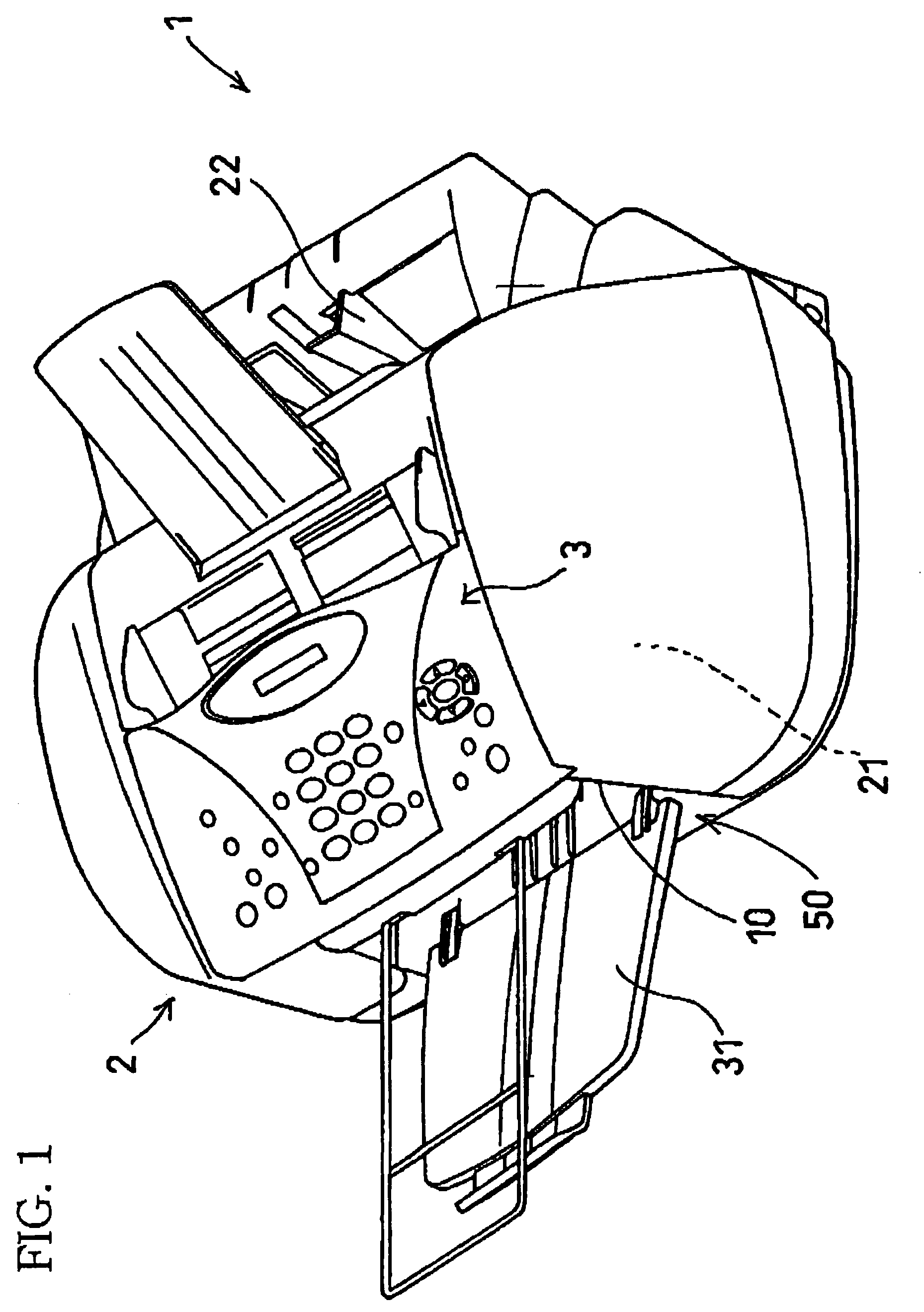
[0043]FIG. 1 shows a multifunction apparatus (multiplex apparatus) 1 having facsimile, scanner, copier and printer functions. This multifunction apparatus 1 is equipped with a feeding device 10 which is constructed according to an embodiment of the invention.

[0044]The multifunction apparatus 1 has, on an upper face of its main body 2, an operating panel 3 equipped with an indicator display and various keys such as ten keys and function keys which are manually operable by an operator of the apparatus 1, to input various command signals for various operations (e.g., facsimileing, scanning and copying operations) to be performed by the apparatus 1. The apparatus 1 further has a media supply tray 22 and a media exit tray 31 located on back and front sides of the main body 2, respectively. In an operation with the apparatus 1, a recording medium in the form of a paper sheet P is supplied through the media supply tray 22 so that the paper sheet P is slid on a slant surface of the media su...


PUM


Abstract

A feeding device for feeding a recording medium in a feed direction, including: a drive roller having an annular recess; and a driven roller rotatably held and positioned such that a radially outer end portion of the driven roller is positioned within the annular recess of the drive roller. The driven roller is displaceable away from the drive roller, so that the recording medium is fed to pass between the drive and driven rollers, with the recording medium being gripped by the radially outer end portion of the driven roller and the radially outer end portion of the drive roller. The feeding device further includes an overlap-amount limiter including a contact portion which is positioned within the annular recess and which is, during absence of the recording medium between the drive and driven rollers, held in contact at its surface with the radially outer end portion of the driven roller, for thereby limiting an overlap amount by which the radially outer end portion of the driven roller overlaps with the radially outer end portion of the drive roller.

Description

[0001]This application is based on Japanese Patent Application No. 2003-84795 filed in Mar. 26, 2003, the content of which is incorporated hereinto by reference.BACKGROUND OF THE INVENTION[0002]1. Field of the Invention[0003]The present invention relates in general to a feeding device for feeding a paper sheet or other recording medium on which desired patterns of images or characters are printed by an inkjet print head.[0004]2. Discussion of Related Art[0005]As a feeding device for feeding a paper sheet in an inkjet printer, there is known a device including (a) a drive roller which is disposed on a downstream side of a recording portion of an inkjet print head as viewed in a feed direction of the paper sheet, and (b) a driven roller which is opposed to the drive, roller, so that the drive and driven rollers operate with each other to grip the paper sheet and feed the paper sheet in the feed direction. The driven roller is provided by a gear-like or toothed roller which has a plura...

Claims


Application Information

Patent Timeline
IPC IPC(8): B65H29/70B41J11/02B41J13/00B41J13/02B65H5/06B65H29/20
CPCB41J13/02B65H5/06B65H2404/1316B65H2404/1415B65H2404/143B65H2404/1441B65H2601/251
Inventor KAWAI, TAKAMITSU
Owner BROTHER KOGYO KK
Why Eureka
Try Eureka