
Passive wireless pressure sensor for harsh environments

Active Publication Date: 2018-12-27
UNIV OF FLORIDA RES FOUNDATION INC
View PDF2 Cites 22 Cited by
  • Summary
  • Abstract
  • Description
  • Claims
  • Application Information

AI Technical Summary

Benefits of technology

The patent describes a passive wireless pressure sensor that can operate in harsh environments. The sensor is made with materials like sapphire for the handle and diaphragm, and platinum for the ground plane and antenna elements. The antenna element can use circular polarization for increased contrast against background. The sensor is designed to be passive and wireless, meaning it requires no internal energy sources and has no wires attached to it. The technical effect of this patent is a more durable, reliable, and versatile wireless pressure sensor that can withstand harsh environments and provide accurate readings.

Problems solved by technology

A sensor capable of operating in a harsh environment may be exposed to high temperatures, vibrations, ionizing radiation, and / or chemical exposure.
High cycle fatigue (HCF), caused by pressure fluctuations in the air flow across the turbine blades and vanes, is the primary source of component failure in gas turbines.

Method used


Image

  • Passive wireless pressure sensor for harsh environments
  • Passive wireless pressure sensor for harsh environments
  • Passive wireless pressure sensor for harsh environments

Examples


example 1

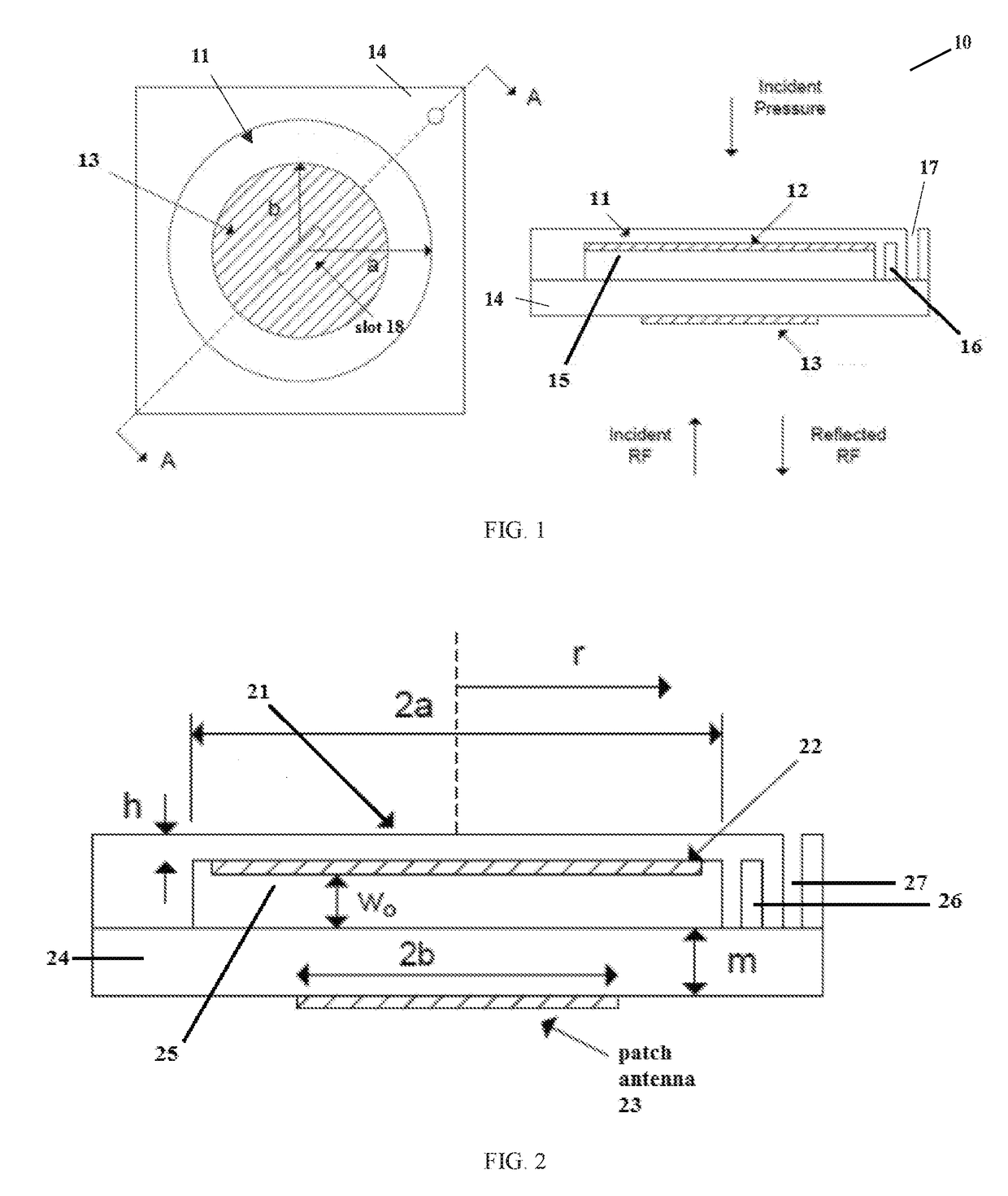
[0116]In FIG. 1, the antenna radius b can be between 2 and 4 mm such that the antenna is large enough to resonate in the X-band, but small enough to allow 1 mm between the diaphragm and the edge of a 10 mm×10 mm die. The diaphragm thickness h is preferably between 15 and 50 μm to support a nominal air gap depth or a cavity depth of up to 35 μm. The diaphragm thickness for the sapphire-based high temperature pressure sensor was fixed at 50 μm as a commercially available part. The electrical operating frequency f was bounded between 13 and 16 GHz such that the antenna operated within its dynamic range, around 15 GHz.

example 2

[0117]Optimization of the diaphragm was performed using commercially available software. The demonstration sensor was designed such that two diaphragm sizes (e.g., 7.6 mm and 6.4 mm) satisfy corresponding pressure requirements (e.g., 3 kPa and 6 kPa) for a pre-determined maximum displacement of 13.5 μm. The optimized design parameters for the demonstration sensor are given in Table I.

TABLE ISummary of optimization results for demonstration sensor.ParameterVariablePmax = 3 kPaPmax = 6 kPaDiaphragm Diameter2a7.6mm6.4mmDiaphragm Thicknessh35μm35μmCavity Depthwa15μm15μmMaximum Displacementwpk,nl13.5μm13.5μmAntenna Diameter2b5.8mm5.8mmNom. Operating Frequencyfo14.9GHz14.9GHz

example 3

[0118]FIGS. 14 through 19 show data (in graphical form) from simulations that were conducted assuming the use of a 5.7 mm circular patch antenna. This information can be used to optimize sensors of the embodiments of the present invention for particular applications.

[0119]FIG. 14 shows the predicted (or simulated) resonant frequency of a pressure sensor as a function of the average air gap (nominal or deflected) depth. It can be seen that there is a linear relationship between the resonant frequency and the average air gap depth, which makes it easier to extract the sensed pressure since the pressure is linearly related to the gap depth, as shown in equation (2).

[0120]FIG. 15 shows the predicted (or simulated) RCS and quality factor (Q factor) as a function of the slot width. The slot width can be selected to obtain the highest RCS (for better sensing) and the highest Q factor (for better sensitivity). The electrical sensitivity of the pressure sensor, as shown in equation (16), is ...


PUM


Abstract

Methods and apparatuses for measuring static and dynamic pressures in harsh environments are disclosed. A pressure sensor according to one embodiment of the present invention may include a diaphragm constructed from materials designed to operate in harsh environments. A waveguide may be operably connected to the diaphragm, and an electromagnetic wave producing and receiving (e.g., sensing) device may be attached to the waveguide, opposite the diaphragm. A handle may be connected between the diaphragm and the waveguide to provide both structural support and electrical functionality for the sensor. A gap may be included between the handle and the diaphragm, allowing the diaphragm to move freely. An antenna and a ground plane may be formed on the diaphragm or the handle. Electromagnetic waves may be reflected off the antenna and detected to directly measure static and dynamic pressures applied to the diaphragm.

Description

CROSS-REFERENCE TO RELATED APPLICATIONS[0001]This patent application claims priority to Provisional Application Ser. No. 62 / 522,830, filed Jun. 21, 2017 which is incorporated herein by reference in its entirety.GOVERNMENT SUPPORT[0002]This invention was made with government support under Grant No. DE-FE0012370 awarded by Department of Energy. The government has certain rights in the invention.BACKGROUND[0003]A sensor capable of operating in a harsh environment may be exposed to high temperatures, vibrations, ionizing radiation, and / or chemical exposure. A high-temperature gas turbine is one example of a harsh environment. The measurement of temperature, pressure, fuel flow, and rotor speed is vital in assessing or monitoring the state of high-temperature gas turbines. High cycle fatigue (HCF), caused by pressure fluctuations in the air flow across the turbine blades and vanes, is the primary source of component failure in gas turbines. The ability to locally measure pressure fluctua...

Claims


Application Information

Patent Timeline
IPC IPC(8): G01L1/14G01L9/00B81B3/00H01Q13/10
CPCG01L1/148G01L9/0042B81B3/0021H01Q13/106B81B2201/0264B81C2201/0143B81B7/02H01Q1/002H01Q1/2208H01Q9/0428G01L9/0047G01L9/0073G01L9/0077
Inventor ROGERS, JOHN E.SHEPLAK, MARKYOON, YONG KYUJUDY, JACK
Owner UNIV OF FLORIDA RES FOUNDATION INC
Learn More