
Agricultural working machine

Active Publication Date: 2018-12-27
CLAAS E SYST GMBH
View PDF4 Cites 7 Cited by
  • Summary
  • Abstract
  • Description
  • Claims
  • Application Information

AI Technical Summary

Benefits of technology

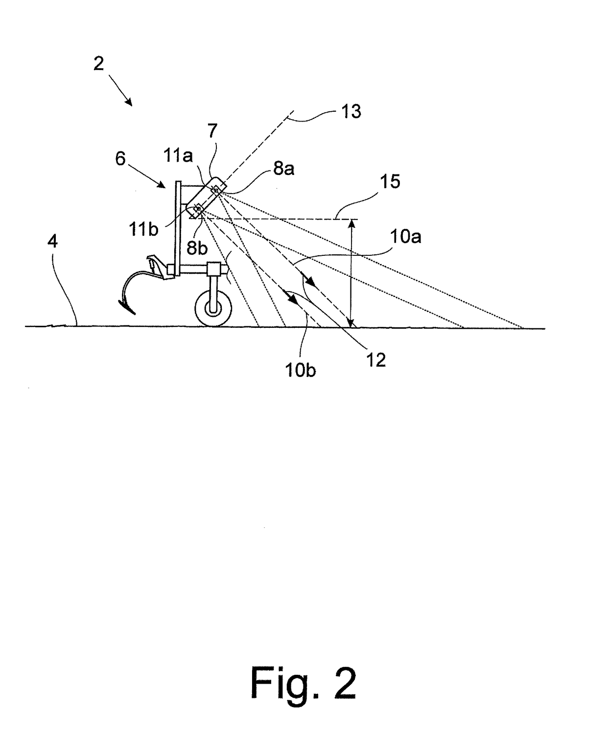
The invention is about improving the accuracy of an agricultural working machine by designing and refining it to increase the accuracy of crop field passage. The 3D camera is positioned in a way that its optical centers are inclined with respect to the horizontal plane, which allows for better detection of vertically growing plants and rows. The camera system is also adjustable, making it possible to adapt to different types of plants and crop. The sensor data collected by the camera system can be used by a driver assistance system to automatically control the machine and optimize its orientation with respect to the rows of plants.

Problems solved by technology

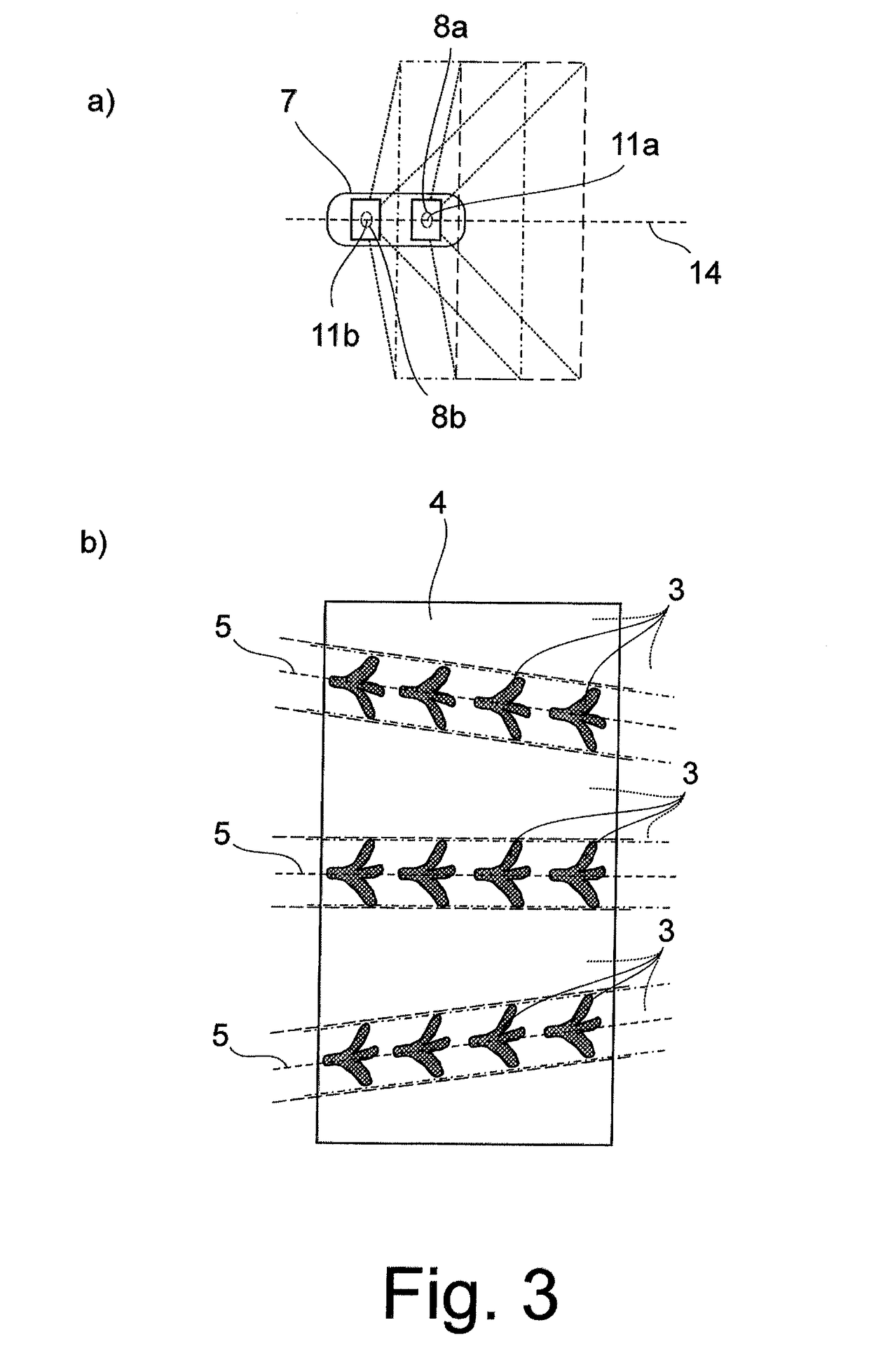
However, if rows of plants are to be traveled along, for example in order to work the ground between the rows of plants, the detection of the rows of plants or their position is relatively imprecise, since the camera lenses detect the particular row of plants from different directions due to the distance between the camera lenses, i.e., the so-called base.
This results in a certain fuzziness of the recorded image and, therefore, an inaccuracy in the 3D information.

Method used


Image

  • Agricultural working machine
  • Agricultural working machine
  • Agricultural working machine

Examples


Embodiment Construction

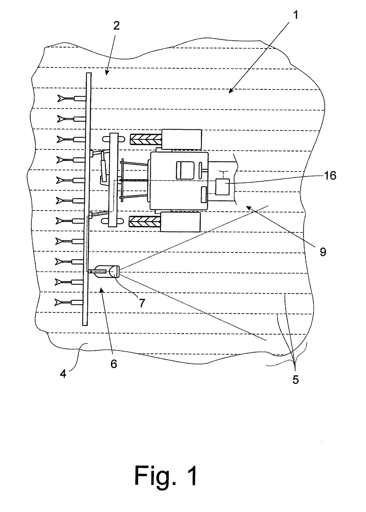
[0022]The approach according to the invention can be applied on a wide range of agricultural working machines, in particular self-propelled agricultural working machines. These include towing machines, in particular tractors, and harvesting machines, in particular combine harvesters, forage harvesters, or the like. In the exemplary embodiment which is depicted and, in this respect, is preferred, the agricultural working machine 1 is a tractor which is equipped in the usual way with an agricultural working unit 2 in the form of a mounted device. In this case, the agricultural working unit 2 is, for example, a mechanical hoe or a cultivator. The comments made with respect to a tractor or such an agricultural working unit apply similarly for all other types of agricultural working machines or agricultural working units.

[0023]The agricultural working machine 1 and the agricultural working unit 2 are operated by an operator, i.e., the driver, wherein a driver assistance system 16 is prov...


PUM


Abstract

An agricultural working machine, in particular a tractor, has at least one agricultural working unit for working a crop field including a multitude of useful plants, and a camera system which includes a 3D camera. The camera system is configured for generating with the 3D camera 3D information regarding the crop field by recording stereoscopic image pairs along two different viewing axes. The viewing axes proceed from optical centers of the 3D camera, which are connected to each other by a baseline that is inclined relative to the horizontal.

Description

CROSS-REFERENCE TO RELATED APPLICATIONS[0001]This application claims priority under 35 USC 119 of German Patent Application No. 10 2017 113 726.2, filed on Jun. 21, 2017, the disclosure of which is herein incorporated by reference.BACKGROUND OF THE INVENTION[0002]The invention relates to an agricultural working machine.[0003]The term “agricultural working machine” is to be broadly understood in the present case. It includes not only harvesting machines such as combine harvesters and forage harvesters, but also towing vehicles such as tractors, or the like.[0004]Within the scope of the increasing automation of agricultural working machines, such machines are now frequently equipped with camera systems and other sensor systems, in order to assist the operator during driving and in performing agricultural work. In particular, agricultural working units of the agricultural working machine, i.e., components and devices, in particular mounted devices utilized for performing or assisting i...

Claims


Application Information

Patent Timeline
IPC IPC(8): H04N13/204H04N13/289G06T7/90H04N13/257
CPCH04N13/204H04N13/289G06T7/90H04N13/257A01B69/008A01B63/008H04N2013/0077G06T2207/30188G06T7/60G06T7/593G06T2207/10012H04N2213/001G06T2207/10024A01B69/001
Inventor JENSEN, MARTIN ANDREAS FALKLISOUSKI, PAVELANDERSEN, GERT LYSGAARDBLAS, MORTEN RUFUS
Owner CLAAS E SYST GMBH
Learn More