Metal powder atomization manufacturing processes

a technology of metal powder and manufacturing process, which is applied in the direction of improving process efficiency, increasing energy efficiency, and improving flowability. it can solve the problems of clogging and/or sticking pipes, and affecting the flowability of powder in the form of agglomerates, so as to improve the flowability and facilitate the use

Pending Publication Date: 2019-01-03
AP&C ADVANCED POWDERS & COATINGS
View PDF7 Cites 23 Cited by
  • Summary
  • Abstract
  • Description
  • Claims
  • Application Information

AI Technical Summary

Benefits of technology

[0005]By contrast, metal powders having improved flowability are desirable for various reasons. For example, they can be used more easily in powder metallurgy processes as additive manufacturing and coatings.

Problems solved by technology

These agglomerates can be detrimental when used in applications that require of fine reactive metal powders.
Furthermore, reactive powder with poor flowability can cause pipes clogging and / or stick on the walls of an atomization chamber of an atomizing apparatus or on the walls of conveying tubes.
Moreover, powders in the form of agglomerates are more difficult to sieve when separating powder into different size distributions.
Manipulation of powder in the form of agglomerates also increases the safety risks as higher surface area translates into higher reactivity.

Method used


Image

  • Metal powder atomization manufacturing processes
  • Metal powder atomization manufacturing processes
  • Metal powder atomization manufacturing processes

Examples


experiment 1

[0212]Four different lots of powder were produced by plasma atomization under the same experimental conditions except for the composition of the atomization mixture contacting the heated metal source.

[0213]The atomizing gas is high purity argon (>99.997%).

[0214]In Tests 1 and 2, only the atomizing gas was used to contact the heated metal source during the atomization process.

[0215]In Test 3, air was injected to the high purity argon to form an atomization mixture of 80 ppm of air with argon. Heated metal was contacted with the atomization mixture during the atomization process.

[0216]In Test 4, O2 was injected to the high purity argon to form an atomization mixture of 50 ppm of O2 with argon. Heated metal was contacted with this second atomization mixture during the atomization process.

[0217]After contacting with the atomizing gas (Test 1 and 2) or the atomization mixture (Test 3 and 4), formed raw reactive metal powder is sieved to isolate the 15-45 μm particle size distributions.

[0...

experiment 2

[0231]Heat treatment was performed a posteriori on already-formed metal powder that was formed from a process in which additive gas was not used.

[0232]More specifically, the already-formed metal powder was heated in air atmosphere at about 250° C. for 12 hours. It was expected that this heating would cause addition of oxygen to surface of particles of the raw metal powder and increase the thickness of the native oxide layer.

[0233]It was observed that oxidation / nitridation a posteriori did not produce a similar result to that of contacting the additive gas in the atomization zone of an atomization process. The improvement of the flowability of the metal powder was not observed.

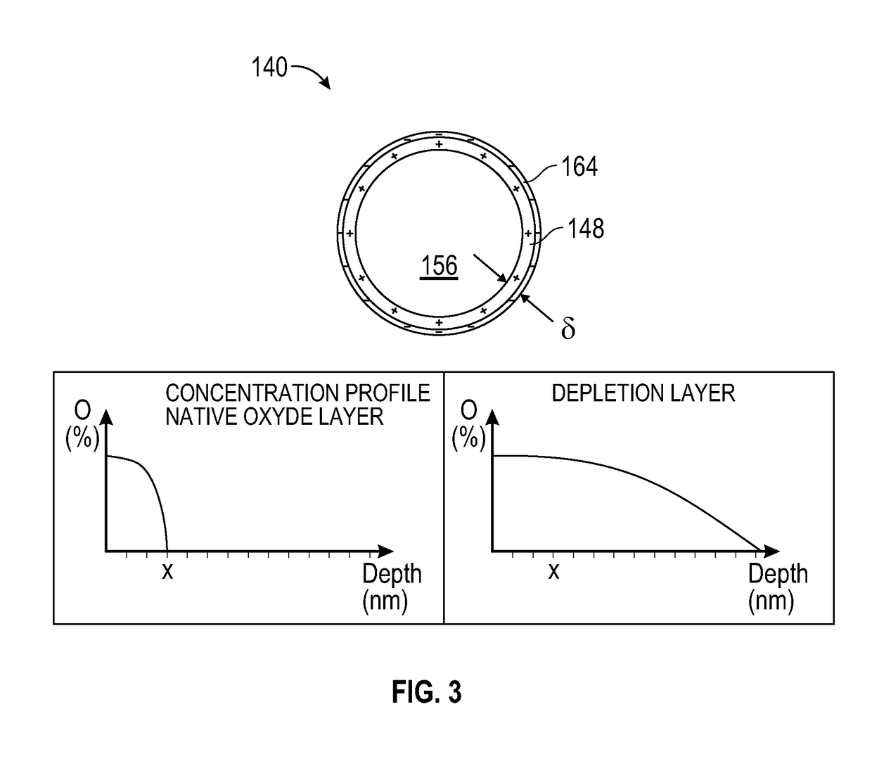
[0234]It seems that a posteriori heating of already-formed metal powder will only thicker the native oxide layer and did not have the ability to provide a sufficient deep and depletion oxide / nitride layer on the particle. The thicker oxide layer will also remain quasi stoichiometric and will not be able to prov...


PUM

PropertyMeasurementUnit
particle size distributionaaaaaaaaaa

Abstract

There are provided reactive metal powder atomization manufacturing processes. For example, such processes include providing a heated metal source and contact the heated metal source with at least one additive gas while carrying out the atomization process. Such processes provide raw reactive metal powder having improved flowability. The at least one additive gas can be mixed together with an atomization gas to obtain an atomization mixture, and the heated metal source can be contacted with the atomization mixture while carrying out the atomization process. Reactive metal powder spheroidization manufacturing processes are also provided.

Description

CROSS-REFERENCE TO RELATED APPLICATIONS[0001]The present application claims priority to U.S. 62 / 247,794 filed on Oct. 29, 2015, which is hereby incorporated by reference in its entirety.FIELD OF THE DISCLOSURE[0002]The present disclosure relates to the field of production of spheroidal powders such as reactive metal powders. More particularly, it relates to methods and apparatuses for preparing reactive metal powders by having improved flowability.BACKGROUND OF THE DISCLOSURE[0003]Typically, the desired features of high quality reactive metal powders will be a combination of high sphericity, density, purity, flowability and low amount of gas entrapped porosities. Fine powders are useful for applications such as 3D printing, powder injection molding, hot isostatic pressing and coatings. Such fine powders are used in aerospace, biomedical and industrial fields of applications.[0004]A powder having poor flowability may tend to form agglomerates having lower density and higher surface a...

Claims


Application Information

Patent Timeline
Patent Type & Authority Applications(United States)
IPC IPC(8): B22F9/08B22F9/04B22F9/14B22F1/00B22F1/02B22F1/052B22F1/14B22F1/16
CPCB22F9/082B22F9/04B22F9/14B22F1/0014B22F1/02B22F2009/0828B22F2009/0848B22F2201/04B22F2201/03B22F2201/02B22F2201/50B22F2202/13B22F2998/10B22F2999/00B01J2/02C22C1/0408C22C1/0416C22C1/0458B22F2009/0824B22F1/052B22F1/14B22F1/16Y02P10/25B22F2201/10B22F2201/11B22F2201/12B22F2201/013B22F2201/016B22F2201/05
Inventor LAROUCHE, FREDERICMARION, FREDERICBALMAYER, MATTHIEU
Owner AP&C ADVANCED POWDERS & COATINGS
Why Eureka
Try Eureka