Backlight module and display device

a backlight module and display device technology, applied in the field of backlight modules and display devices, can solve the problems of increasing thermal power consumption and other problems, and achieve the effect of improving the heat-radiating effect of the backlight module and introducing out the heat of the light strip

Active Publication Date: 2019-01-03
WUHAN CHINA STAR OPTOELECTRONICS TECH CO LTD
View PDF3 Cites 2 Cited by
  • Summary
  • Abstract
  • Description
  • Claims
  • Application Information

AI Technical Summary

Benefits of technology

[0014]In comparison with the prior art, in the present disclosure, the heat-radiating sheet is disposed on a surface of a side of the light strip circuit board of the light strip deviating from the light guiding plate and includes the extension portions, and the extension portions may be selectively connected to other heat sources or heat-radiating sources, thereby introducing out heat of the light strip and improving the heat-radiating effect of the backlight module.

Problems solved by technology

As the number of LED chips used in a single backlight unit increases, thermal power consumption also increases.

Method used


Image

  • Backlight module and display device
  • Backlight module and display device
  • Backlight module and display device

Examples


embodiment 1

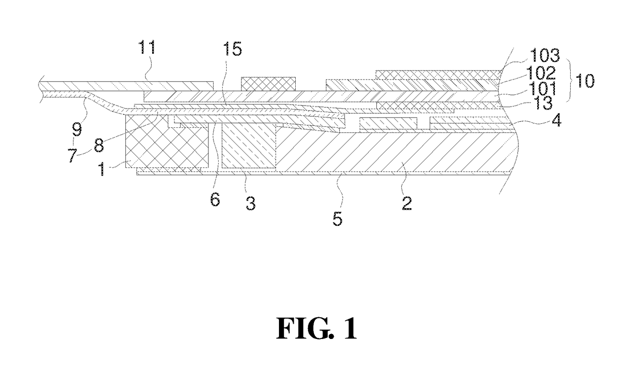
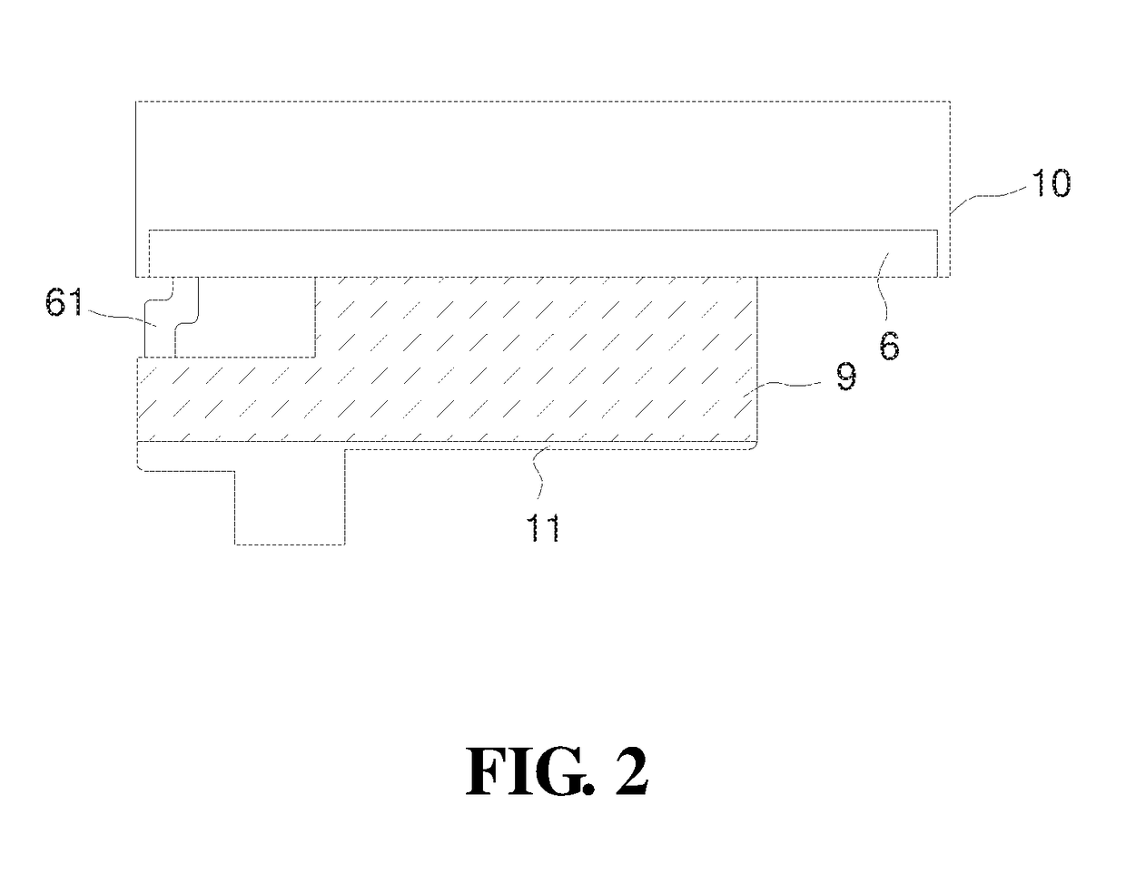
[0025]As shown in FIGS. 1 and 2, the display device of the present disclosure includes a display panel 10, a printed circuit board 11 connected to the display panel 10, and the backlight module, the display panel 10 and the backlight module being connected and fixed therebetween by a frame adhesive 15, wherein:

[0026]the display panel 10 includes an array substrate 101, a color filter substrate 102 disposed opposite to the array substrate 101, and a liquid crystal encapsulated therebetween (not shown in the figures), a lower polarizer sheet 13 being disposed on the array substrate 101 and an upper polarizer sheet 103 being disposed on the color filter substrate 102;

[0027]the backlight module includes the rubber frame 1, the light guiding plate 2 disposed in the rubber frame 1, the light strip 3 located on a light incident side of the light guiding plate 2, the optical film set 4 disposed on a surface of a side of the light guiding plate 2, and a reflecting sheet 5 disposed on a surfa...

embodiment 2

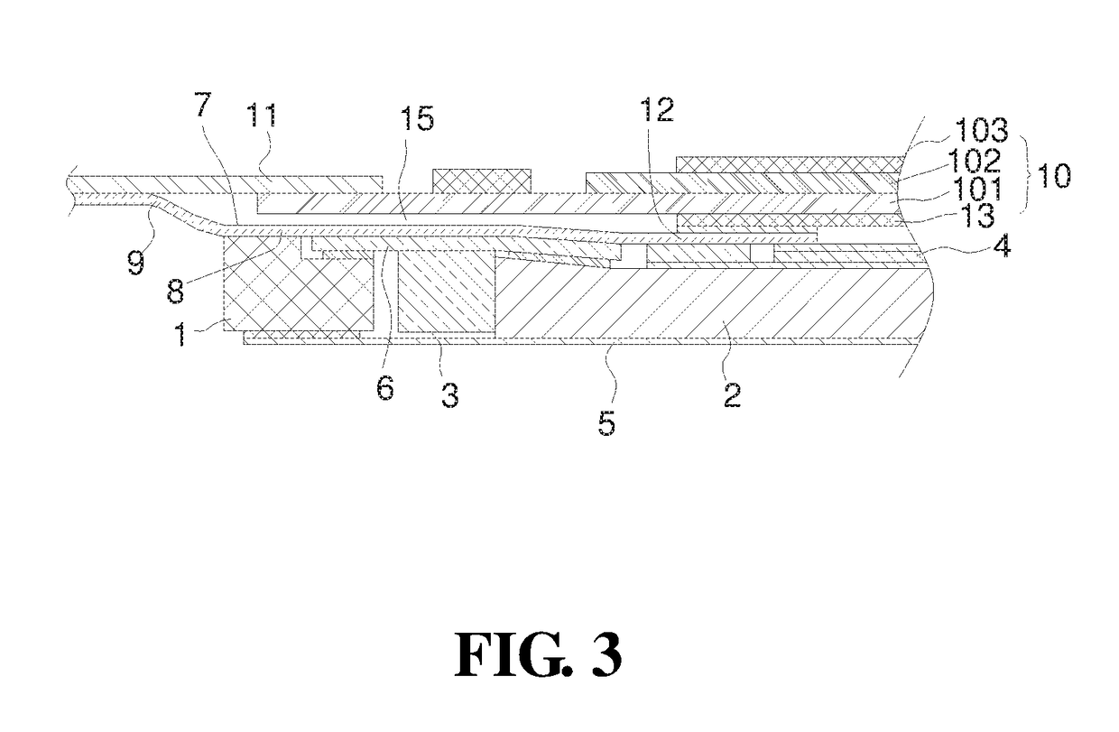
[0032]As shown in FIGS. 3 and 4, a display device of the present disclosure includes a display panel 10, a printed circuit board 11 connected to the display panel 10, and the backlight module, the display panel 10 and the backlight module being connected and fixed therebetween by a frame adhesive 15, wherein:

[0033]the display panel 10 includes an array substrate 101, a color filter substrate 102 disposed opposite to the array substrate 101, and a liquid crystal encapsulated therebetween (not shown in the figures), a lower polarizer sheet 13 being disposed on the array substrate 101 and an upper polarizer sheet 103 being disposed on the color filter substrate 102;

[0034]the backlight module includes a rubber frame 1, a light guiding plate 2 disposed in the rubber frame 1, a light strip 3 located on a light incident side of the light guiding plate 2, an optical film set 4 disposed on a surface of a side of the light guiding plate 2, and a reflecting sheet 5 disposed on a surface of a s...

embodiment 3

[0040]As shown in FIG. 5, the display device of the present disclosure includes a display panel 10, a printed circuit board 11 connected to the display panel 10, and the backlight module, the display panel 10 and the backlight module being connected and fixed therebetween by a “□” adhesive 15, wherein:

[0041]the display panel 10 includes an array substrate 101, a color filter substrate 102 disposed opposite to the array substrate 101, and a liquid crystal encapsulated therebetween (not shown in the figures), a lower polarizer sheet 13 being disposed on the array substrate 101 and an upper polarizer sheet 103 being disposed on the color filter substrate 102;

[0042]the backlight module includes a rubber frame 1, a light guiding plate 2 disposed in the rubber frame 1, a light strip 3 located on a light incident side of the light guiding plate 2, an optical film set 4 disposed on a surface of a side of the light guiding plate 2, and a reflecting sheet 5 disposed on a surface of a side of ...


PUM


Abstract

The present disclosure provides a backlight module including a rubber frame, a light guiding plate disposed in the rubber frame, a light strip located on a light incident side of the light guiding plate, an optical film set disposed on a surface of a side of the light guiding plate, and a reflecting sheet disposed on a surface of a side of the light guiding plate deviating from the optical film set. The reflecting sheet is fixed on the rubber frame by a double-faced adhesive, the light strip includes a light strip circuit board, a heat-radiating sheet is disposed on a surface of a side of the light strip circuit board deviating from the light guiding plate, and the heat-radiating sheet includes a fitting portion attached onto the light strip circuit board and a bendable first extension portion extending to an outside of the rubber frame.

Description

TECHNICAL FIELD[0001]The present disclosure relates to a liquid crystal display panel technology, and particularly, to a backlight module and a display device.BACKGROUND ART[0002]At present, intelligent display terminals are increasingly pursuing a high-resolution and high-brightness liquid crystal display module, which undoubtedly needs to use a higher-brightness backlight unit (BLU). Based on a current LED brightness level, a design of the high-brightness backlight unit needs to use more LEDs or adopt a double crystal LED to implement brightness improvement. As the number of LED chips used in a single backlight unit increases, thermal power consumption also increases. How to resolve a problem of LED heat is a subject worthy of study. A heat-radiating structure of the existing backlight module is to add a graphite heat-radiating sheet under a reflecting sheet or a metal back plate which is at the backlight bottom, and a defect thereof is: a thickness of the module increases.SUMMARY...

Claims


Application Information

Patent Timeline
Patent Type & Authority Applications(United States)
IPC IPC(8): F21V8/00
CPCG02B6/0085G02B6/0055G02B6/0088
Inventor ZHANG, ZHENZHEN
Owner WUHAN CHINA STAR OPTOELECTRONICS TECH CO LTD
Why Eureka
Try Eureka