Harmonic shunting electric motor with faceted shaft for improved torque transmission

Active Publication Date: 2019-01-03
TRANE INT INC
View PDF6 Cites 9 Cited by
  • Summary
  • Abstract
  • Description
  • Claims
  • Application Information

AI Technical Summary

Benefits of technology

[0019]In some embodiments, the method includes transferring heat from the rotor shaft to the cooling fluid. In some embodiments, the method includes providing a plurality of longitudinal facets defined on the rotor shaft to which at least one of the plurality of magnets is fixed. In some embod

Problems solved by technology

Each of these methods is costly, bulky, and can result on overall system derating (e.g., insulated gate bipolar transistor (IGBT) and associated power module d

Method used


Image

  • Harmonic shunting electric motor with faceted shaft for improved torque transmission
  • Harmonic shunting electric motor with faceted shaft for improved torque transmission
  • Harmonic shunting electric motor with faceted shaft for improved torque transmission

Examples


Example

[0035]The various aspects of the present disclosure mentioned above are described in further detail with reference to the aforementioned figures and the following detailed description of exemplary embodiments.

DETAILED DESCRIPTION

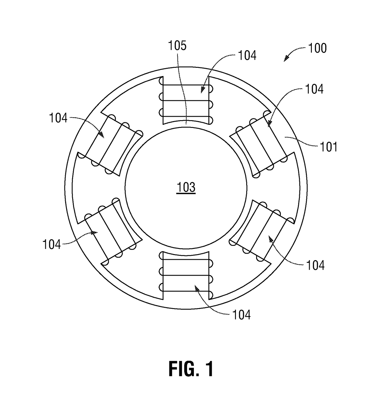
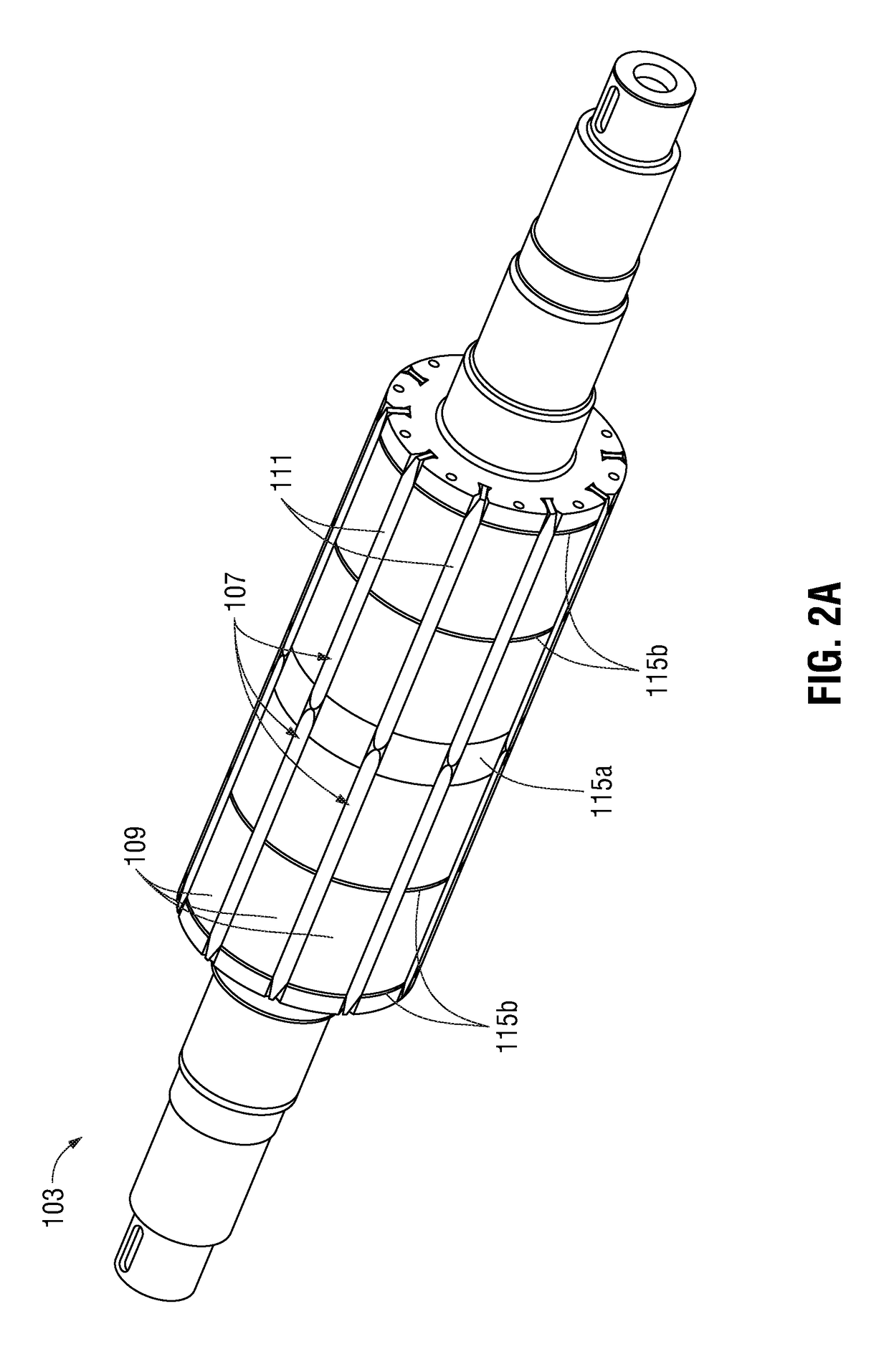
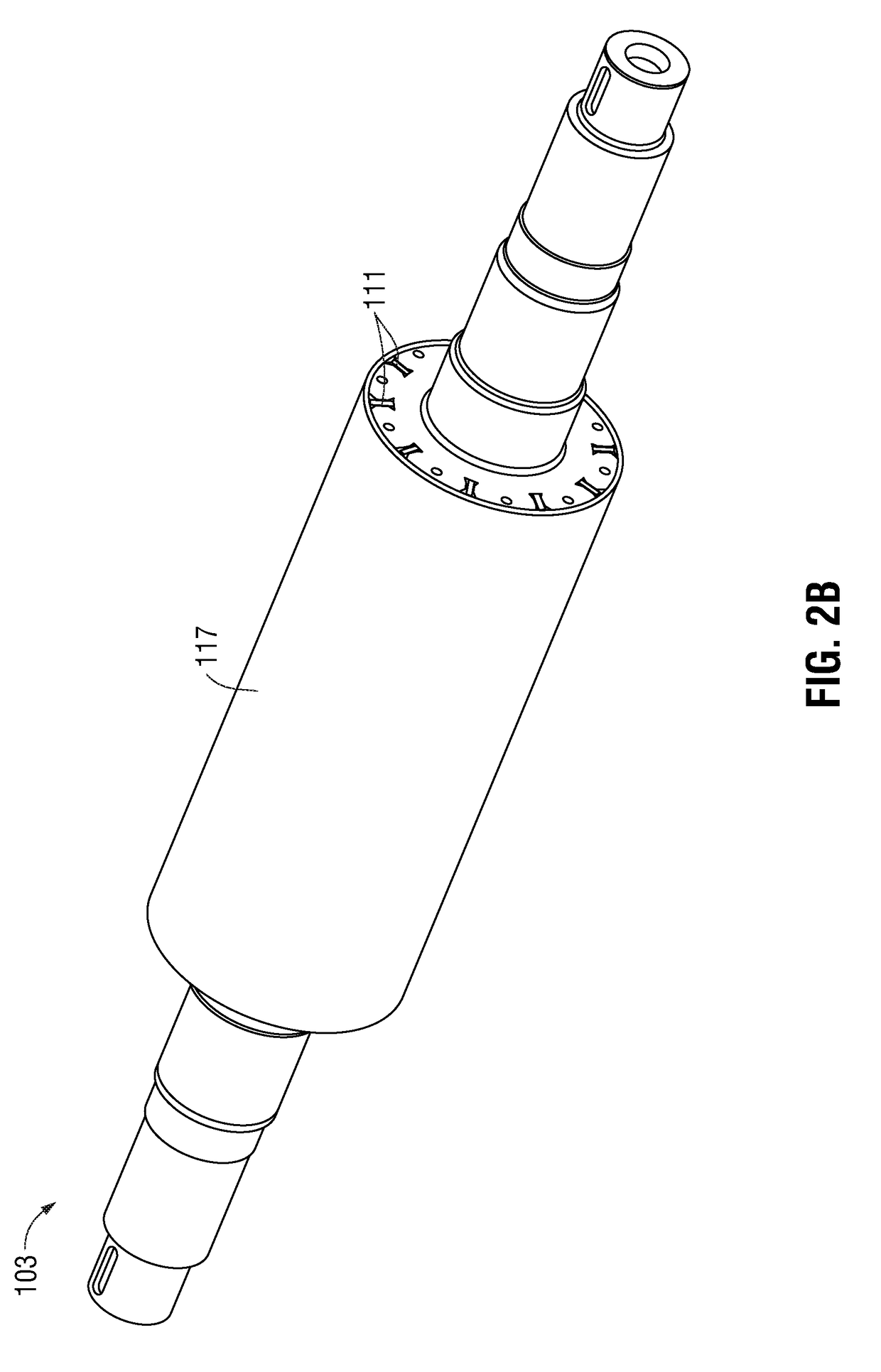
[0036]Particular illustrative embodiments of the present disclosure are described hereinbelow with reference to the accompanying drawings, however, the disclosed embodiments are merely examples of the disclosure, which may be embodied in various forms. Well-known functions or constructions and repetitive matter are not described in detail to avoid obscuring the present disclosure in unnecessary or redundant detail. Therefore, specific structural and functional details disclosed herein are not to be interpreted as limiting, but merely as a basis for the claims and as a representative basis for teaching one skilled in the art to variously employ the present disclosure in virtually any appropriately detailed structure. In this description, as well as in the dra...


PUM


Abstract

Disclosed are an electric motor and a simplified variable speed drive system which renders the use of filtering components in a motor drive circuit unnecessary and increases torque transfer from permanent magnets of the rotor to the output shaft. The motor includes a fluid gap between the rotor and the stator configured to receive a cooling fluid, such a refrigerant. A plurality of radially-abutting, bread loaf-shaped magnets having a flat base are respectively fixed to a plurality of longitudinally oriented mounting facets provided on the shaft to provide maximum torque transfer from the magnets to the shaft. An eddy shield disposed between the faceted shaft and the magnets thermally shunts high frequency harmonics from the magnets to the shaft and cooling fluid. The rotor components are mechanically secured by a sleeve disposed around the rotor.

Description

BACKGROUND1. Technical Field[0001]The present disclosure is directed to systems, apparatus, and methods for thermal management of electrical machines (e.g., compressor motors in chillers), and in particular, an improved variable speed electric motor and drive system that eliminates the need for drive current harmonic filters.2. Background of Related Art[0002]In AC electric motors, motor temperature rise results from the circulation of high frequency currents which do not contribute to magnetic flux production in the air gap, but rather dissipate in the motor stator and / or rotor as Joule loss. Existing methods to mitigate this issue include installation of passive filters (e.g., L, LC, etc.) between the motor and drive, use of multi-level inverters, pulse width modulation (PWM) optimization patterns and increasing switching frequencies. Each of these methods is costly, bulky, and can result on overall system derating (e.g., insulated gate bipolar transistor (IGBT) and associated powe...

Claims


Application Information

Patent Timeline
IPC IPC(8): H02K11/01H02K9/20H02K1/27H02K1/28F25B31/00
CPCH02K11/01H02K9/20F25B31/006H02K1/28H02K1/278H02K21/16H02K1/223H02K16/02H02K11/012H02K9/227
Inventor PETERSON, CHARLES J.ABBOTT, RUSSELL T.
Owner TRANE INT INC
Why Eureka
Try Eureka