Fluid End for Frac Pump

a frac pump and flue end technology, which is applied in the direction of piston pumps, positive displacement liquid engines, borehole/well accessories, etc., can solve the problems of limited porousness of shale rock, limestone and coal beds, and inability to easily flow hydrocarbons, etc., to achieve the effect of reducing the cross-sectional area

Active Publication Date: 2019-01-10
BJ ENERGY SOLUTIONS LLC FORMERLY TES ASSET ACQUISITION LLC
View PDF23 Cites 156 Cited by
  • Summary
  • Abstract
  • Description
  • Claims
  • Application Information

AI Technical Summary

Benefits of technology

[0047]Additional embodiments provide multi-unit reciprocating pumps having a tapered shim installed a suction manifold. The tapered shim supp

Problems solved by technology

Hydrocarbons, however, are not always able to flow easily from a formation to a well.
Other formations, however, such as shale rock, limestone, and coal beds, are only minimally porous.
The formation may contain large quantities of hydrocarbons, but production through a conventional well may not be commercially practical because hydrocarbons flow though the formation and collect in the well at very low rates.
Pressure builds rapidly to the point where the formation fails and begins to fracture.
Continued pumping of fluid into the formation will tend to cause the initial fractures to widen and extend further away from the well bore, creating flow paths to the well.
The harsh operating conditions and frequent servicing means that the typical fracturing operation rarely relies on a single pump.
Such forces, over time, induce cracking, both visible and microscopic, that can lead to failure.

Method used


Image

  • Fluid End for Frac Pump
  • Fluid End for Frac Pump
  • Fluid End for Frac Pump

Examples


Embodiment Construction

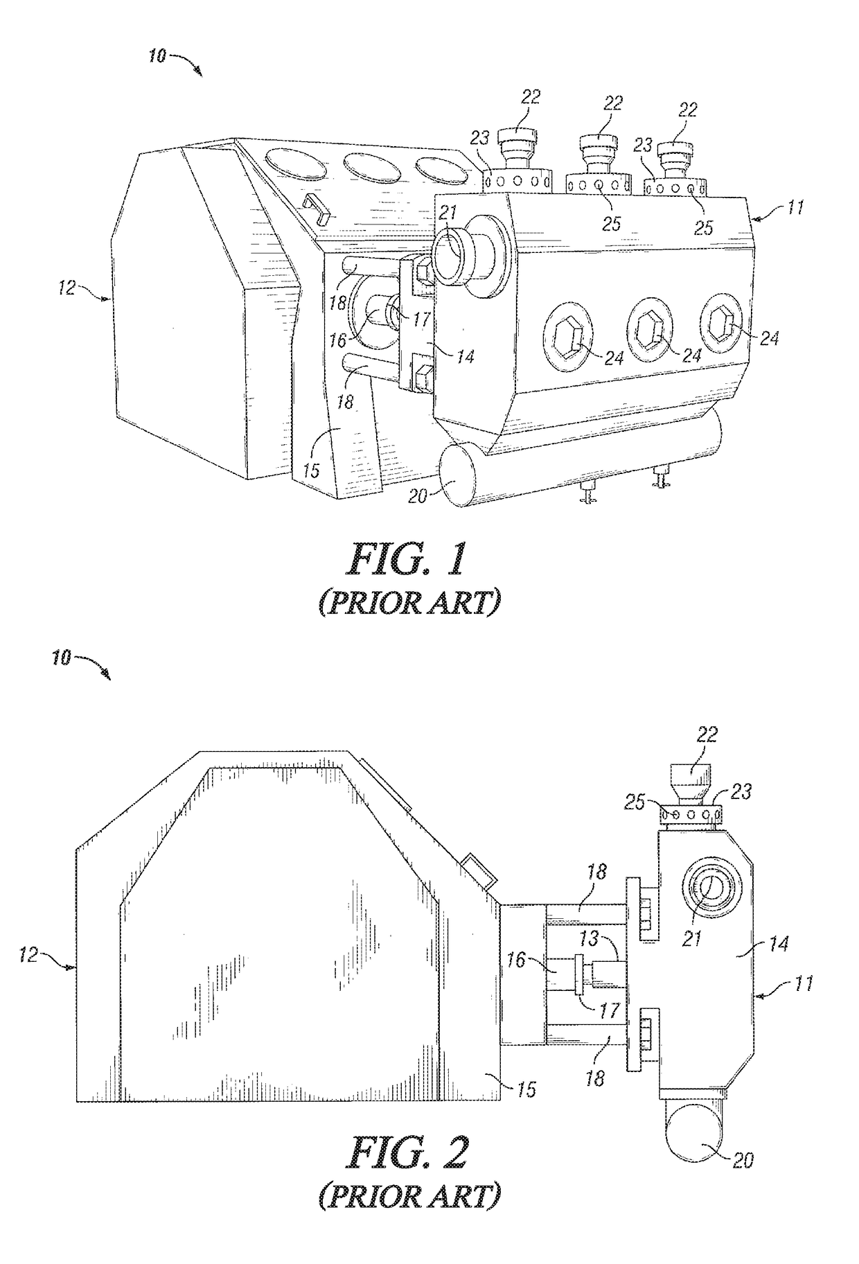
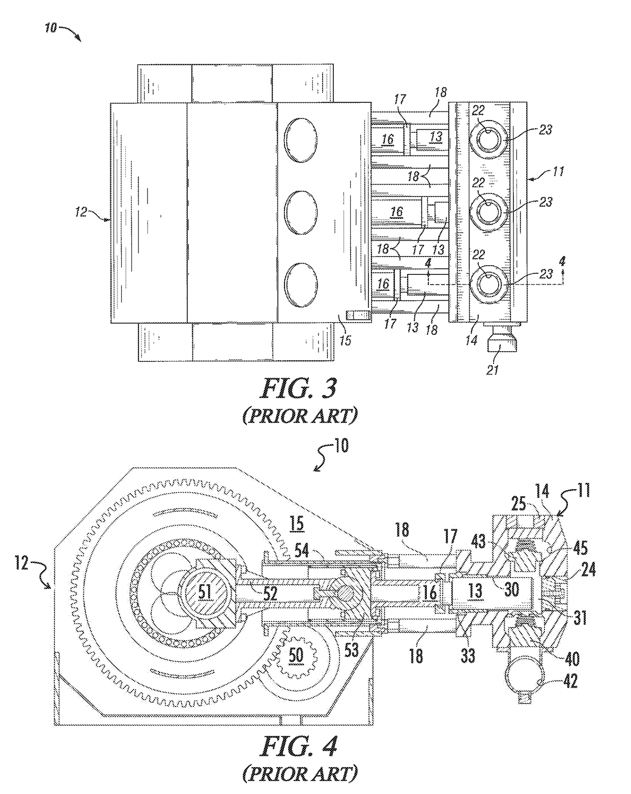
[0109]The subject invention, in various aspects and embodiments, is directed generally to high pressure, high volume reciprocating pumps, such as those used in fracturing oil and gas wells, and in particular, to various aspects and features of the fluid end of such pumps. Specific embodiments will be described below. For the sake of conciseness, however, all it features of an actual implementation may not be described or illustrated. In developing any actual implementation, as in any engineering or design project, numerous implementation-specific decisions must be made to achieve a developers' specific goals. Decisions usually will be made consistent within system-related and business-related constraints, and specific goals may vary from one implementation to another. Development efforts might be complex and time consuming and may involve many aspects of design, fabrication, and manufacture. Nevertheless, it should be appreciated that such development projects would be a routine eff...


PUM


Abstract

Frac pumps have valve seats and bodies. The valve seats comprise a cylindrical body and an annular seat surface. The body has an axial passage and external threads adapted to engage internal threads in a fluid end block of the frac pump. The annular seat surface is at an end of the body and is adapted to engage a valve body. The valve bodies comprise a head and a compressible seal. The head provides a valve surface adapted to engage the valve seat. The compressible seal is carried on the head radially inward of the valve surface and is adapted to engage the valve seat.

Description

[0001]The present invention relates in general to high pressure, high volume reciprocating pumps used in the oil and gas industry to fracture or “frac” a formation, and in particular, to improved designs for the fluid ends of such pumps.BACKGROUND OF THE INVENTION[0002]Hydrocarbons, such as oil and gas, may be recovered from various types of subsurface geological formations. The formations typically consist of a porous layer, such as limestone and sands, overlaid by a nonporous layer. Hydrocarbons cannot rise through the nonporous layer. Thus, the porous layer forms a reservoir, that is, a volume in which hydrocarbons accumulate. A well is drilled through the earth until the hydrocarbon bearing formation is reached. Hydrocarbons then can flow from the porous formation into the well.[0003]In what is perhaps the most basic form of rotary drilling methods, a drill bit is attached to a series of pipe sections referred to as a drill string. The drill string is suspended from a derrick an...

Claims


Application Information

Patent Timeline
IPC IPC(8): F16K1/42F04B53/10
CPCF16K1/42E21B43/26F04B19/22F04B53/10F04B1/0452F04B1/053F04B1/0538F04B9/045F04B47/04F04B53/1025F04B53/16F16K1/422F16K1/36E21B43/2607
Inventor YEUNG, TONY
Owner BJ ENERGY SOLUTIONS LLC FORMERLY TES ASSET ACQUISITION LLC
Why Eureka
Try Eureka