Wireless charger with structure for directly cooling portable terminal

Inactive Publication Date: 2019-01-10
CPC CO LTD
View PDF2 Cites 16 Cited by
  • Summary
  • Abstract
  • Description
  • Claims
  • Application Information

AI Technical Summary

Benefits of technology

[0005]Accordingly, the present disclosure is conceived to solve the foregoing problems, and an aspect of the present disclosure is to effectively dissipate heat generated while a wireless charger is charging a portable terminal, and thus provide a wireless charger havi

Problems solved by technology

However, a conventional wireless charger available on the market these days has a structure for merely dissipating

Method used


Image

  • Wireless charger with structure for directly cooling portable terminal
  • Wireless charger with structure for directly cooling portable terminal
  • Wireless charger with structure for directly cooling portable terminal

Examples


first embodiment

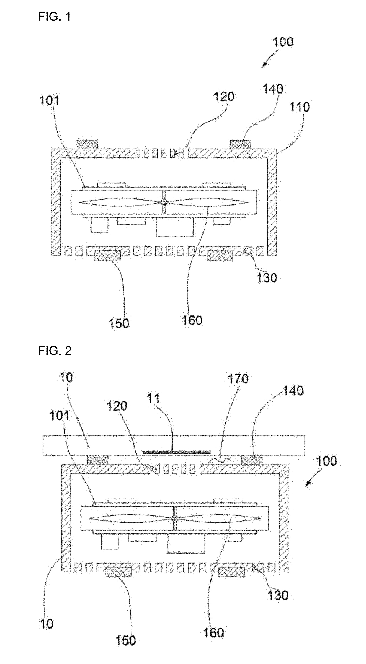
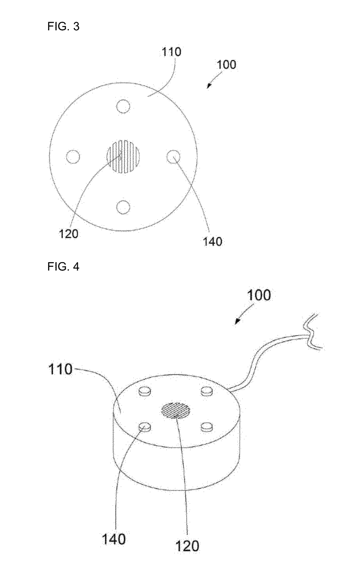
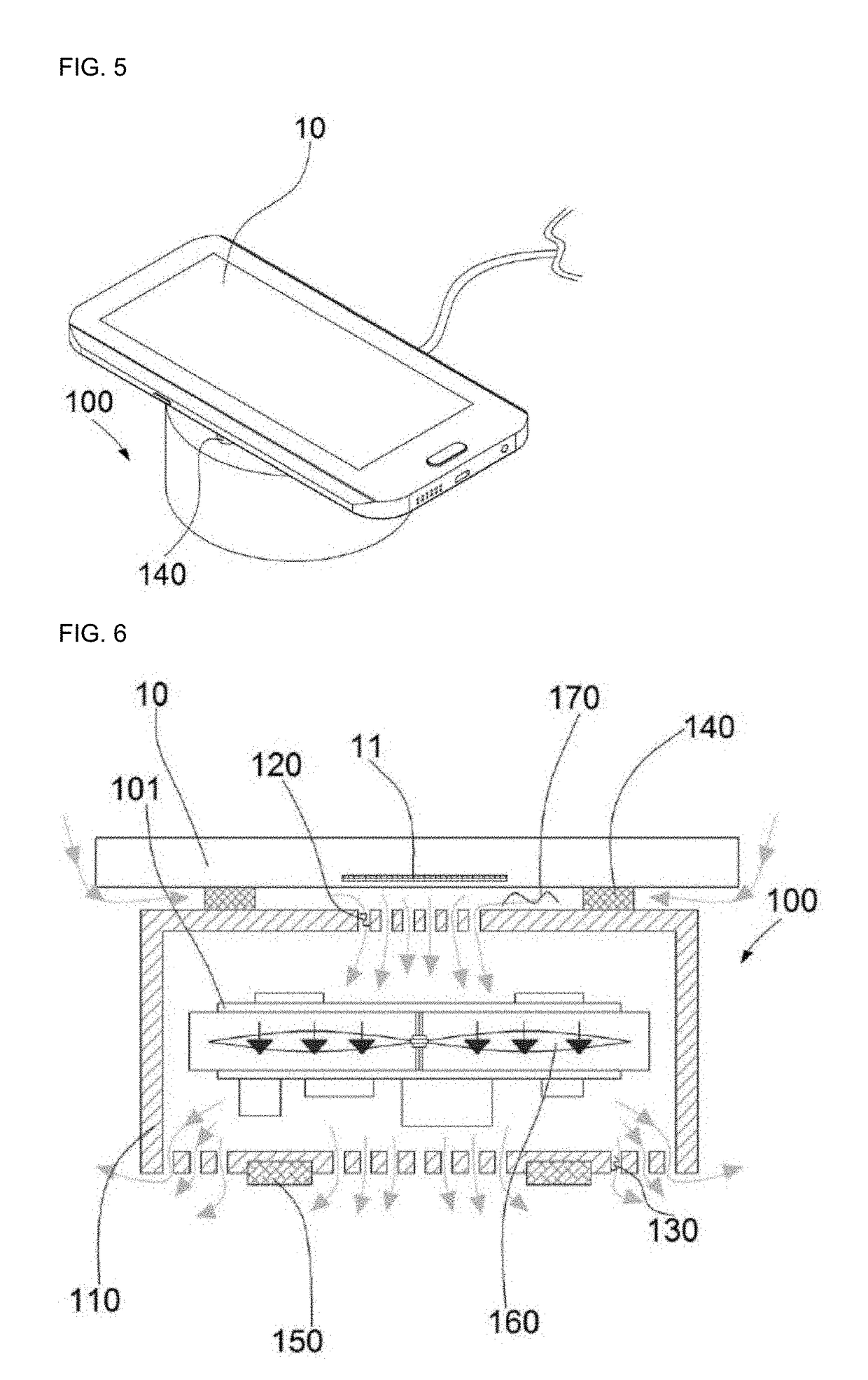
[0027]Referring to FIGS. 1 to 9, a wireless charger having a structure for directly cooling a portable terminal according to the present disclosure includes a charging body 110, a cooling fan 160, a top hole 120, and an outlet hole 130 as a structure to be applicable to a wireless charger 100 for wirelessly charging a portable terminal 10.

[0028]The portable terminal 10 includes a charging patch 11 attached thereto and receiving electric power from a power transmission coil 101 of the wireless charger 100 to charge a battery. While the portable terminal 10 is being wirelessly charged by the wireless charger 100, the charging patch 11 generates heat and thus makes the portable terminal 10 hot.

[0029]The charging body 110 is used to put the portable terminal 10 thereon for charging, and is internally provided with the cooling fan 160 (to be described later. The charging body 110 is formed with the top hole 120 on the top thereof, through which air between the portable terminal 10 put on...

second embodiment

[0050]Referring to FIGS. 10 to 12, a direct cooling projection 240 according to the present disclosure protrudes at a predetermined height from the top of a charging body 210. A plurality of direct cooling projections 240 are spaced apart from one another and protrude from the top of the charging body 210 at the same height,

[0051]Such an upper direct cooling projection 240 is formed with a point contact portion 241 protruding outwardly and convexly from the top thereof. As shown in FIG. 11, when the portable terminal 10 is placed on the direct cooling projection 240, the bottom of the portable terminal 10 is in point-contact with the point contact portion 241.

[0052]Thus, when the portable terminal 10 is put on the direct cooling projection 240, a contact area between the direct cooling projection 240 and the portable terminal 10 is smaller than the area of surface contact. Accordingly, a gap 270 in which air can circulate under the portable terminal 10 is larger, and therefore a coo...

third embodiment

[0053]FIG. 13 is a schematic cross-section view of a wireless charger having a structure for directly cooling a portable terminal according to the present disclosure;

[0054]Referring to FIG. 13, according to the third embodiment of the present disclosure, a top hole 320 is formed to have a trapezoidal shape that becomes wider in a direction from an inner opening side of the charging body 310 toward an outer opening side of the charging body 310, and the outlet hole 330 is formed to have a trapezoidal shape that becomes narrower in a direction from an inner opening side of the charging body 310 toward an outer opening side of the charging body 310.

[0055]With this structure, a large amount of air in the gap can be introduced into the relatively wide opening side of the top hole 320, and a large amount of air in the charging body 310 is discharged through the relatively wide opening side of the outlet hole 330. Then, air in the gap and the charging body 310 is more quickly circulated, a...


PUM


Abstract

According to an aspect of the present disclosure, a wireless charger for wirelessly charging a portable terminal, having a structure for directly cooling the portable terminal, includes: a charging body on which the portable terminal to be charged is put; a top hole which is formed to penetrate a top of the charging body and makes air between the portable terminal put on the charging body and the charging body flow into the charging body so that the portable terminal can be directly cooled; a cooling fan by which the air between the portable terminal put on the charging body and the charging body is introduced into the charging body; and an outlet hole through which the air introduced into the charging body by the cooling fan is discharged outward from the charging body.

Description

CROSS-REFERENCE TO RELATED APPLICATION[0001]This application claims priority from Korean Patent Application No. 10-2017-0086962, filed on Jul. 10, 2017 in the Korean Intellectual Property Office, the disclosure of which is incorporated herein by reference.BACKGROUND OF THE INVENTION(a) Field of the Invention[0002]The present disclosure relates to a wireless charger having a structure for directly cooling a portable terminal.(b) Description of the Related Art[0003]A wireless charger refers to a device for charging a terminal without contact, and is classified into a magnetic induction type and a magnetic resonance type. In general, the wireless charger used in charging a smartphone is the magnetic induction type.[0004]A general wireless charger is internally provided with a coil and the like of generating heat, and thus additionally includes an internal cooling fan and a ventilation hole to dissipate the generated heat. However, a conventional wireless charger available on the market...

Claims


Application Information

Patent Timeline
IPC IPC(8): H05K7/20H02J7/02H02J7/00
CPCH05K7/20145H02J7/025H02J50/12H02J50/10H02J7/0044H04B5/0037H02J2310/22H01F27/025H01F27/085H01F27/2876H02J50/005
Inventor HAN, HYUN SUK
Owner CPC CO LTD
Why Eureka
Try Eureka