
Planetary Countercurrent Chromatography Centrifuge and Mixer-Settler Rotor

a chromatography centrifuge and mixer-settler technology, which is applied in the direction of separation processes, instruments, measurement devices, etc., can solve the problems of insufficient quantitative hplc recovery, limited yield of particular forms, and inability to produce a large amount of semiconductor types, so as to facilitate the seating of gaskets, avoid higher rotor weights, and facilitate the application of uniform pressure

Inactive Publication Date: 2019-01-17
CC BIOTECH
View PDF0 Cites 3 Cited by
  • Summary
  • Abstract
  • Description
  • Claims
  • Application Information

AI Technical Summary

Benefits of technology

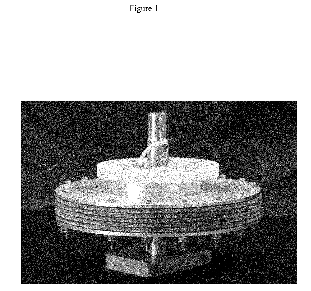
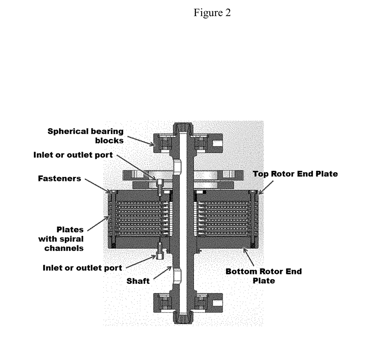
The patent describes a new rotor design for separating larger molecules, such as carbon nanotubes, from mixtures. The rotor consists of a disc made of a durable plastic with radial channels and a rim for securely fitting the rotor components. The rotor is designed to have a high volume and can include a gasket to improve sealing. The gasket is made of an elastomer or rubber and can be deformed or compressed to ensure a good seal. The rotor is oriented vertically to enhance the attainment of phase equilibrium with viscous solvents. The technical effects of this design include improved separation of larger molecules, reduced leaking, better fit among components, and increased run life of the rotor.

Problems solved by technology

Some methods do not produce a high amount of semiconductor types and some methods seed desired types, however, yields of particular forms are limited.
However, HPLC recoveries are not quantitative [7].
But, for more polar molecules, such as, peptides [9] which are soluble and partition well in alcohol solvent systems, coils do not perform as well.
However, there remain issues with rotors disclosed in, for example, U.S. Pat. Nos. 7,892,847 (hereinafter, “the '847 patent,”) and CN 201143392Y, such as, after use at higher centrifugation speed, leaks occurred through gaskets and flow was blocked leading to lower flow rates, even for washes.
Also, friction between and among moving parts generated wear and heat.
However, separating larger molecules, including carbon nanotubes (CNT's), requires higher centrifugation speed.
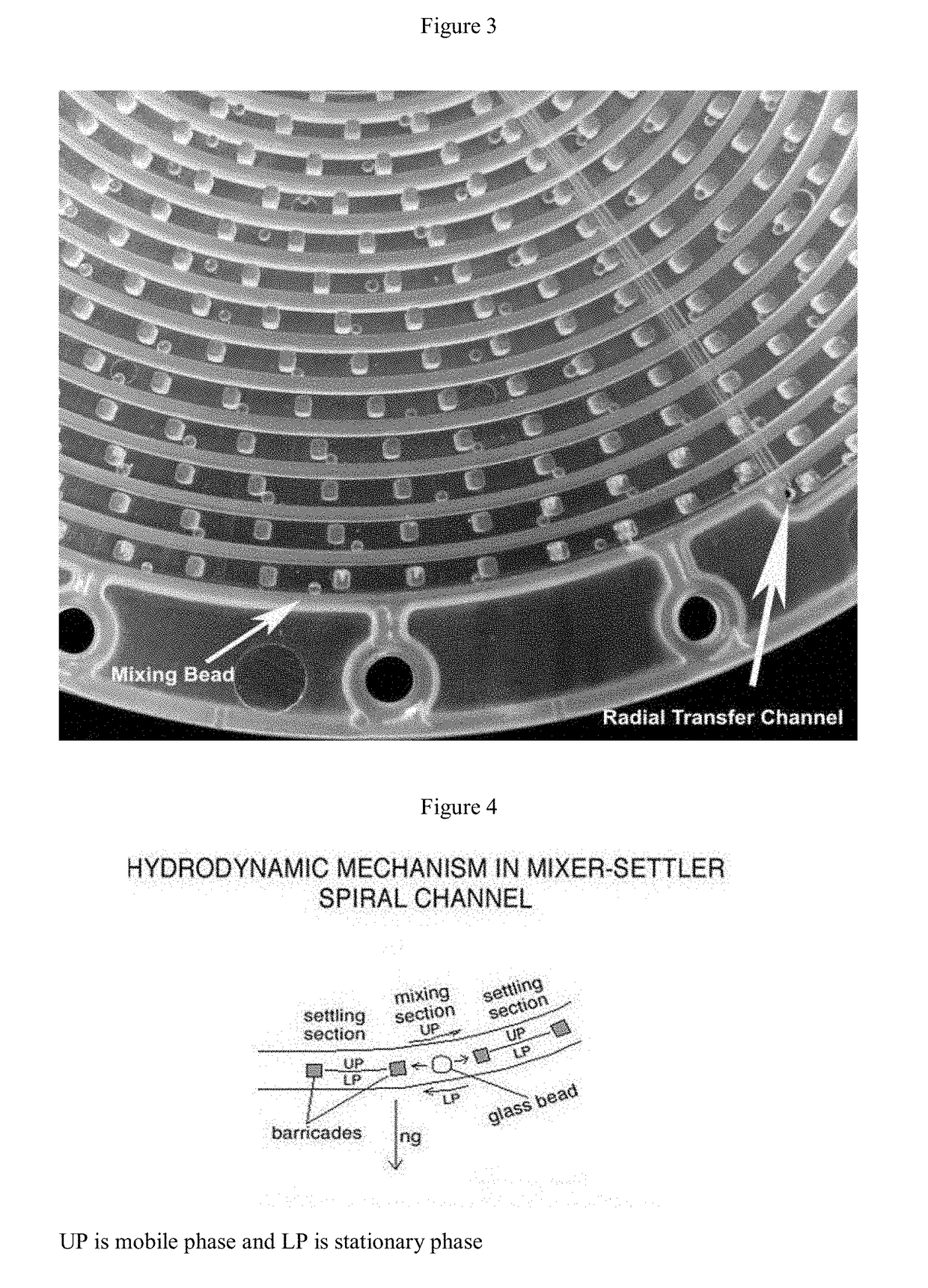
Disks need to be stronger, for example, previous discs were made of polypropylene which warped or deformed throughout a surface area of a disc and mixing glass beads were not secure.

Method used


Image

  • Planetary Countercurrent Chromatography Centrifuge and Mixer-Settler Rotor
  • Planetary Countercurrent Chromatography Centrifuge and Mixer-Settler Rotor
  • Planetary Countercurrent Chromatography Centrifuge and Mixer-Settler Rotor

Examples


example 1

[0118]A prior art mixer-settler spiral disk rotor, was disassembled for parts. Fluid flow had become blocked after use.

[0119]On inspection, the plastic plate or disc was found to have too shallow a return channel underneath, the depth was observed to be less than 1 mm. The soft gasket below the disc had filled the space in the channel and blocked fluid flow.

example 2

[0120]After the rotor of Example 1 was used for about 3 months, leaking was observed through the center towards the shaft.

[0121]It was discerned that screws around the center had been overtightened resulted in breakage of some screws. Gaskets revealed solvent leaked around the screws in the center area, plates and gaskets were not sealed well.

[0122]Screw holes of the bottom end plate were reamed so screws could be tightened without pressure on the screws and on the substance of the bottom end plate, the threads and screw holes. The screws were associated instead with nuts for tightening and a more decentralized pressure on the bottom plate.

example 3

[0123]An assembled rotor with a new gasket below a disc where radial slits in the gasket marry with channels in a disc, also included compressible VITON® gaskets. A smaller gasket or washer of interest about the central portions of a rotor minimized or prevented leaking.

[0124]A mixer-settler spiral disk with gasketing can be used to separate large molecules, such as, proteins as well as separation of species of CNT's using an ATPS system.


PUM

PropertyMeasurementUnit
revolution radiusaaaaaaaaaa
outer diameteraaaaaaaaaa
lengthsaaaaaaaaaa

Abstract

A mixer-settler countercurrent chromatography centrifuge and rotor of increased capacity is described.

Description

[0001]Portions of the research described herein were supported in part by NIH grant no. R43AT008296-01 to CC Biotech, Rockville, Md.BACKGROUND OF INVENTION[0002]Carbon nanotubes (CNT), carbon-carbon extended polymers with fused sp2 orbitals, have aromatic properties [1,2]. Sheets are known as graphenes and can form tubes, nanotubes. Tubular forms are of various diameter from about 1 rim to a few hundred urn and have lengths of about 500 nm to several thousands of nanometers. Nanotubes are single-walled or multi-walled, having anisotropic structures. Nanotubes exhibit conductive or semiconductor properties, and are chiral. The hexagonal array of the atoms is in a left-handed or a right-handed spiral pattern. Dimensions of patterns of a hexagonal honeycomb lattice are described by vectors, m and n, where nanotubes of certain values of m and n being semiconducting. A, ‘zig-zag,’ pattern where m=0 and an, ‘arm chair,’ pattern where n=m (metallic) are non-chiral structures. Longer CNT's ...

Claims


Application Information

Patent Timeline
Patent Type & Authority Applications(United States)
IPC IPC(8): B01D15/22B01D15/18G01N30/42B01D15/24
CPCB01D15/22B01D15/1807B01D15/247G01N30/42B01D15/1892
Inventor KNIGHT, MARTHAFELDMAN, BENCABAHUG, ERIC
Owner CC BIOTECH
Learn More