Auto-loading underwater firearm

a firearm and auto-loading technology, applied in the field of underwater firearms, to achieve the effect of reducing the amount of gas expelled through the muzzle, reducing drag, and lessening the pressure shockwav

Active Publication Date: 2019-01-17
SPIKES TACTICAL
View PDF21 Cites 10 Cited by
  • Summary
  • Abstract
  • Description
  • Claims
  • Application Information

AI Technical Summary

Benefits of technology

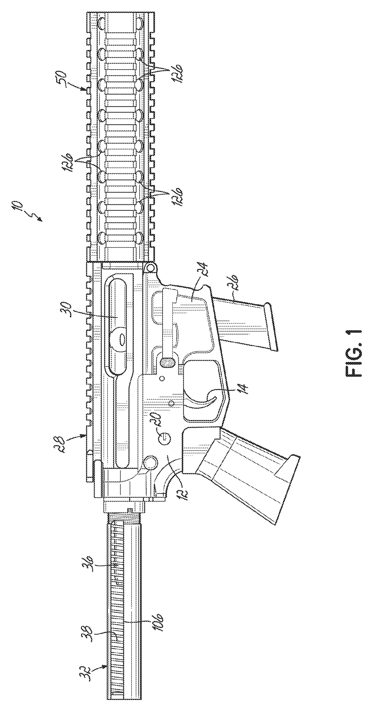
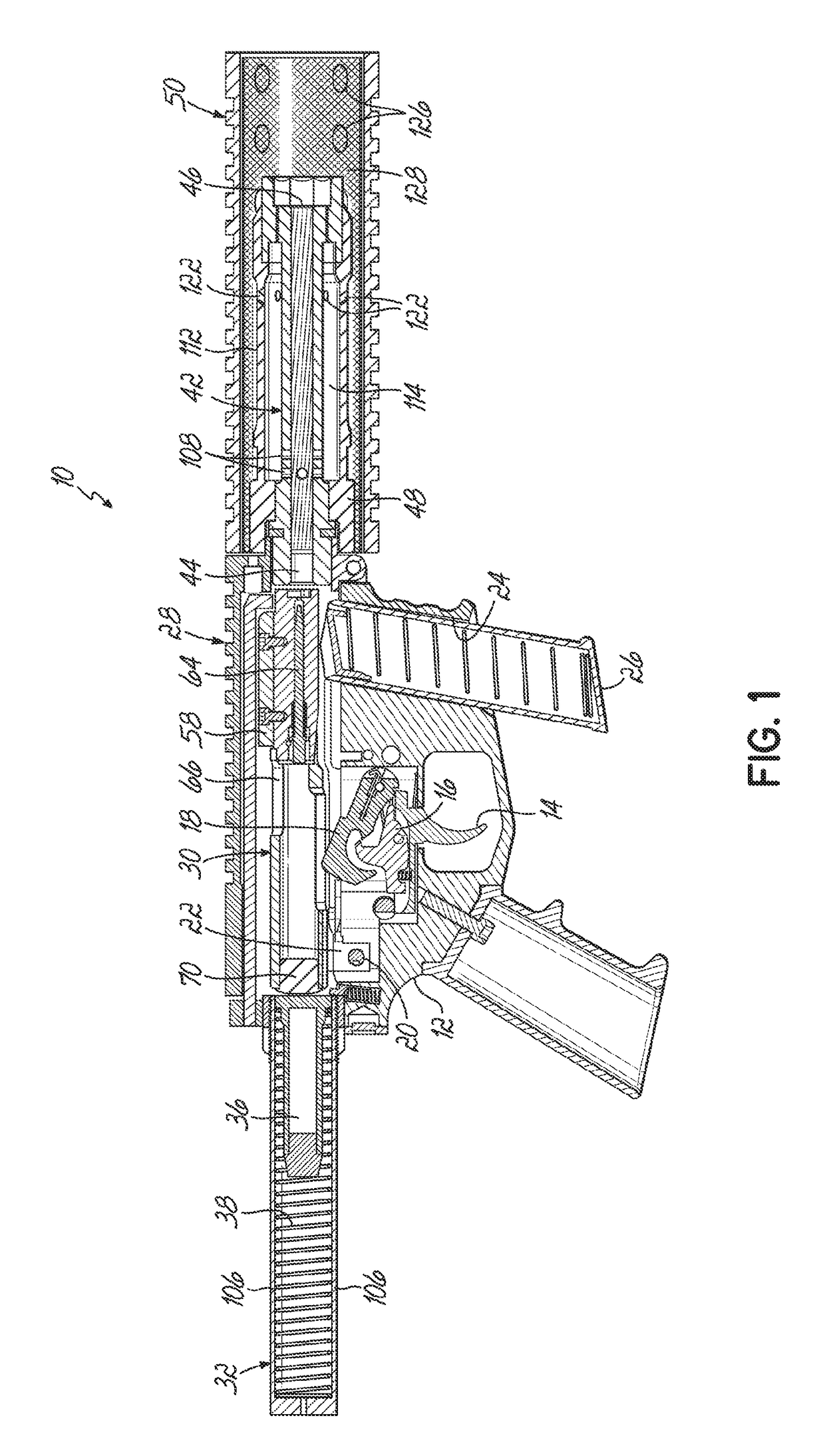
[0009]An impulse wave disruptor system may be integrated into a ported barrel assembly so that a muzzle-attached device is unnecessary. This can include a barrel having a bore, a muzzle at a forward end, and at least one barrel port. A housing external to the bore defines at least a first gas expansion chamber in fluid communication with the barrel port and having at least one exhaust port. The barrel bore and expansion chamber are flooded when underwater and propellant gases that push a projectile through the bore are vented through the barrel port to forcefully expel water from the expansion chamber through the exhaust port and to vent propellant gases. This delays the release of gases released to surrounding water and reduces the amount of gas expelled through the muzzle. Other devices that separate and disrupt the bubble of propellant gases being released into the surrounding liquid medium may be used to further lessen the pressure shockwave.
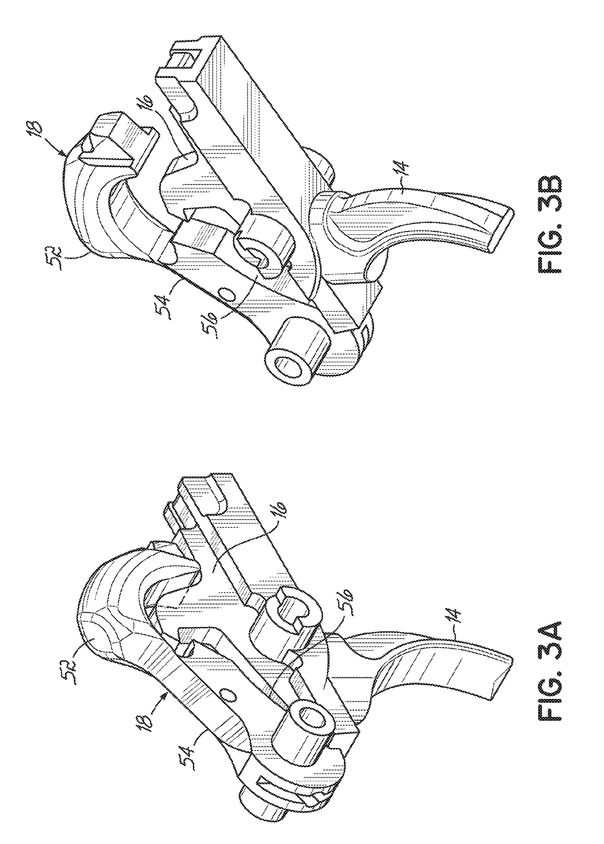
[0010]Parts of the fire control system may include a streamlined or hydrodynamic profile to reduce drag as they move through a water-filled environment. Parts of the blowback bolt may be profiled to allow the passage, bypassing, or venting of fluid as the part is moved rapidly through a water-filled chamber. Likewise, the recoil buffer tube may be ported (or skeletonized) to allow controlled venting of water from and into the housing as the action cycles. Other challenges, including the reliable ejection of a spent casing from the upper receiver through the dense fluid medium of water.

Problems solved by technology

Other challenges, including the reliable ejection of a spent casing from the upper receiver through the dense fluid medium of water.

Method used


Image

  • Auto-loading underwater firearm
  • Auto-loading underwater firearm
  • Auto-loading underwater firearm

Examples


Embodiment Construction

[0033]With reference to the drawing figures, this section describes particular embodiments and their detailed construction and operation. Throughout the specification, reference to “one embodiment,”“an embodiment,” or “some embodiments” means that a particular described feature, structure, or characteristic may be included in at least one embodiment. Thus, appearances of the phrases “in one embodiment,”“in an embodiment,” or “in some embodiments” in various places throughout this specification are not necessarily all referring to the same embodiment. Furthermore, the described features, structures, and characteristics may be combined in any suitable manner in one or more embodiments. In view of the disclosure herein, those skilled in the art will recognize that the various embodiments can be practiced without one or more of the specific details or with other methods, components, materials, or the like. In some instances, well-known structures, materials, or operations are not shown ...


PUM


Abstract

A shockwave impulse disruptor system for use in an underwater firearm. The system includes a barrel having a bore, a muzzle, and at least one barrel port. A housing is external to the bore and defines at least a first gas expansion chamber. The expansion chamber is in fluid communication with the barrel port and has at least one exhaust port. The barrel bore and expansion chamber are flooded when underwater. Propellant gases that push a projectile through the bore are vented through the barrel port to force water from the expansion chamber through the exhaust port and to vent propellant gases. This delays the release of gases to surrounding water and reduces the amount of gas expelled through the muzzle.

Description

RELATED APPLICATIONS[0001]This application claims priority to U.S. Provisional Patent Application No. 62 / 526,607, filed Jun. 29, 2017, and incorporates the same herein by reference.TECHNICAL FIELD[0002]The present invention relates to a firearm for use underwater. More particularly, it relates to a firearm capable of semiautomatic or fully automatic fire without the need for creating or maintaining an evacuated (dry) barrel or other chambers.BACKGROUND[0003]When a firearm is discharged in the open atmosphere, the rapid release of pressurized propellant gasses through the muzzle creates a soundwave that travels through the air and to the ears of persons nearby. The sound travels by creating a compression wave through the air. This sound impulse can be reduced to a hearing-safe level by the use of a firearm noise suppressor, which typically includes a series of sealed chambers that temporality capture the high-pressure gas, allowing it to enter the atmosphere more slowly.[0004]Because...

Claims


Application Information

Patent Timeline
Patent Type & Authority Applications(United States)
IPC IPC(8): F41C9/06F41A21/28
CPCF41A21/28F41C9/06F41A3/54F41A3/66F41A19/13F41A19/14F41A19/43F41A21/30
Inventor MYERS, JAMES RANDY
Owner SPIKES TACTICAL
Why Eureka
Try Eureka