Rotational Angle Sensor

a technology of rotational angle sensor and sensor, which is applied in the direction of electrical/magnetically converting sensor output, measuring devices, instruments, etc., can solve the problems of high cross sensitivity of rotational angle sensor and sensitive to interference, and achieve low construction space, easy evaluation, and robust and inexpensive angular rotation.

Active Publication Date: 2019-01-17
ROBERT BOSCH GMBH
View PDF7 Cites 12 Cited by
  • Summary
  • Abstract
  • Description
  • Claims
  • Application Information

AI Technical Summary

Benefits of technology

[0006]Embodiments of the present invention can advantageously make it possible to provide a robust and inexpensive angular rotational sensor which takes up little construction space and with which the sensor signals generated can be easily evaluated.
[0007]Ideas relating to embodiments of the present invention may be regarded as based inter alia on the concepts and findings described below.
[0008]The invention relates to a rotational angle sensor which can be used in particular in an environment with strong magnetic interference fields. For example, the rotational angle sensor can be used in the engine compartment or in the vicinity of the engine compartment of a vehicle, for example for determining a position of a throttle valve, a rotor position of a BLDC motor, a position of a gas pedal or a position of a camshaft. The angular rotational sensor described below is inexpensive, requires a small construction space and is based on a simple measuring principle.
[0009]According to one embodiment of the invention, the rotational angle sensor comprises a stator element with a transmitting coil and at least two receiving coils arranged within the transmitting coil, which are arranged on a circuit board, and a rotor element, which is mounted rotatably about an axis of rotation with respect to the stator element and by way of which the transmitting coil is inductively coupled to the at least two receiving coils, so that the inductive coupling is dependent on a rotational angle between the stator element and the rotor element and the transmitting coil induces at least two angle-dependent alternating voltages in the at least two receiving coils.
[0010]The term “within the transmitting coil” should be understood here as meaning that, in a plane in which the transmitting coil is arranged, the receiving coils are arranged in the plane or in a projection onto this plane within the (outer) contour of the transmitting coil.
[0011]The stator element, which may also carry an evaluation unit, may for example be arranged opposite the end of a shaft on which the rotor element is fastened. The rotor element may carry one or more induction segments, which are moved along with the shaft, cover the receiving coils and as a result change the inductance of the receiving coils or the respective inductive coupling between the transmitting coil and the receiving coils. If the transmitting coil is energized with an alternating voltage, alternating voltages of an amplitude that depends on the respective inductive coupling are induced in the receiving coils. The evaluation unit can then calculate for example a rotational angle signal from these alternating voltages or their amplitudes, which the sensor emits as measurement signals. The rotational angle sensor can in this way be implemented inexpensively, since no expensive magnet is required.

Problems solved by technology

Such sensors also react to external magnetic fields, which are caused for example by a current flowing through power cables arranged alongside, and can be very sensitive to interference.
However, this type of rotational angle sensor may have a high cross sensitivity to installation tolerances (especially tilting of the target).

Method used


Image

  • Rotational Angle Sensor
  • Rotational Angle Sensor
  • Rotational Angle Sensor

Examples


Embodiment Construction

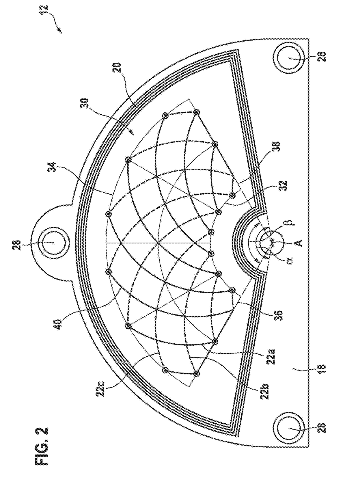
[0044]FIG. 1 shows a rotational angle sensor 10 comprising a stator element 12 and a rotor element 14. The rotor element 14 may be fastened on a shaft 16 of a component, such as for instance a throttle valve, a motor, a camshaft, a gas pedal, etc., or be provided by this shaft 16. The shaft 16 is rotatable about the axis A and the stator element 12 lies opposite the rotor element 14 in the corresponding axial direction. For example, the stator element 12 is fastened on a housing of the component.

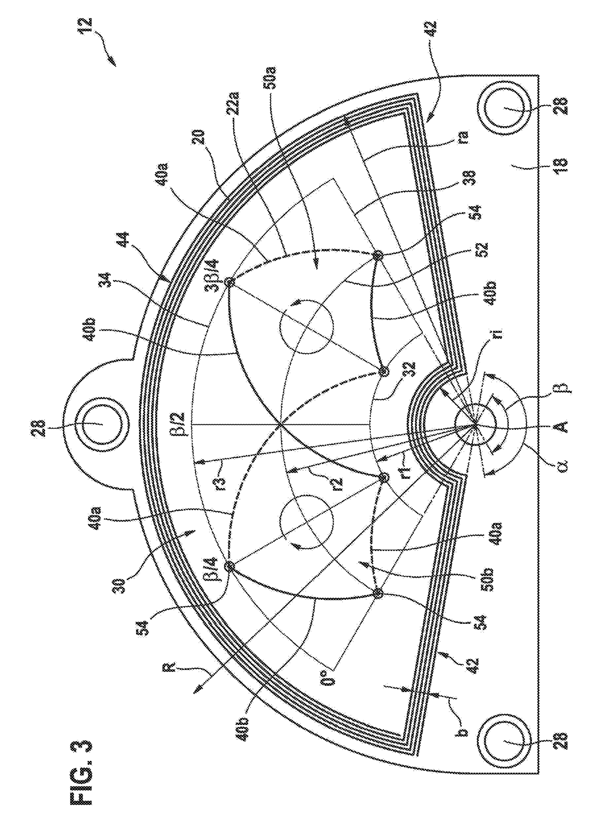
[0045]The stator element 12 comprises a circuit board 18, on which a transmitting coil 20 and a number of receiving coils 22 with conductor tracks are configured on the circuit board 18. The conductor tracks of the coils 20, 22 may be located on both sides of the circuit board 18. The conductor tracks may be electrically connected to one another through the circuit board by means of vias (vertical interconnect accesses). On the circuit board 18 there may be further components for an evaluati...


PUM


Abstract

A rotational angle sensor includes a stator element and a rotor element. The stator element has a transmitting coil and at least two receiving coils that are arranged within the transmitting coil and on a circuit board. The rotor element is mounted for rotation with respect to the stator element about an axis of rotation. The rotor element is configured to inductively couple the transmitting coil to the at least two receiving coils in such a way that the inductive coupling is dependent on a rotational angle between the stator element and the rotor element and the transmitting coil induces at least two angle-dependent alternating voltages in the at least two receiving coils. The rotor element and the at least two receiving coils are configured in such a way that an alternating voltage, the amplitude of which is sinusoidally dependent on the rotational angle, is induced in the receiving coils.

Description

FIELD OF THE INVENTION[0001]The invention relates to a rotational angle sensor, with which for example a rotational angle between a shaft and a further component can be determined. The invention also relates to a stator element for such a rotational angle sensor.PRIOR ART[0002]To measure rotational angles, rotational angle sensors in which a magnet is rotated over a corresponding magnetic field sensor are known for example. The measurement of the magnetic field vector then allows the rotational angle to be deduced. Such sensors also react to external magnetic fields, which are caused for example by a current flowing through power cables arranged alongside, and can be very sensitive to interference.[0003]Another type of rotational angle sensor uses an eddy current effect. In this case, for example, a metallic target is moved over sensor coils, which are supplied with an AC voltage and induce an eddy current in the target. This causes a reduction in the inductances of the sensor coils...

Claims


Application Information

Patent Timeline
Patent Type & Authority Applications(United States)
IPC IPC(8): G01D5/20
CPCG01D5/2053G01D5/2073
Inventor UTERMOEHLEN, FABIANMERZ, ANDREAS
Owner ROBERT BOSCH GMBH
Why Eureka
Try Eureka