
Motor, end cap and manufacturing method thereof

a technology of end caps and end caps, which is applied in the direction of current collectors, dynamo-electric components, control/drive circuits, etc., can solve the problems of high cost and complicated achieve the effect of simple mounting process of end caps, low cost and convenient automatic assembly

Active Publication Date: 2019-01-17
JOHNSON ELECTRIC SA
View PDF0 Cites 3 Cited by
  • Summary
  • Abstract
  • Description
  • Claims
  • Application Information

AI Technical Summary

Benefits of technology

The patent describes a need for a simple and low-cost end cap for electric motors, as well as a method to make it. The end cap has a filter circuit board that is integrated into it or the motor, with conductors and a filter element connected to them. This makes assembly easy and cost-effective. The technical effect is to simplify the construction of electric motors and reduce their cost of production.

Problems solved by technology

As such, the mounting process of the end cap is complicated, not convenient for automatic assembly, and thus has a high cost.

Method used


Image

  • Motor, end cap and manufacturing method thereof
  • Motor, end cap and manufacturing method thereof
  • Motor, end cap and manufacturing method thereof

Examples


Embodiment Construction

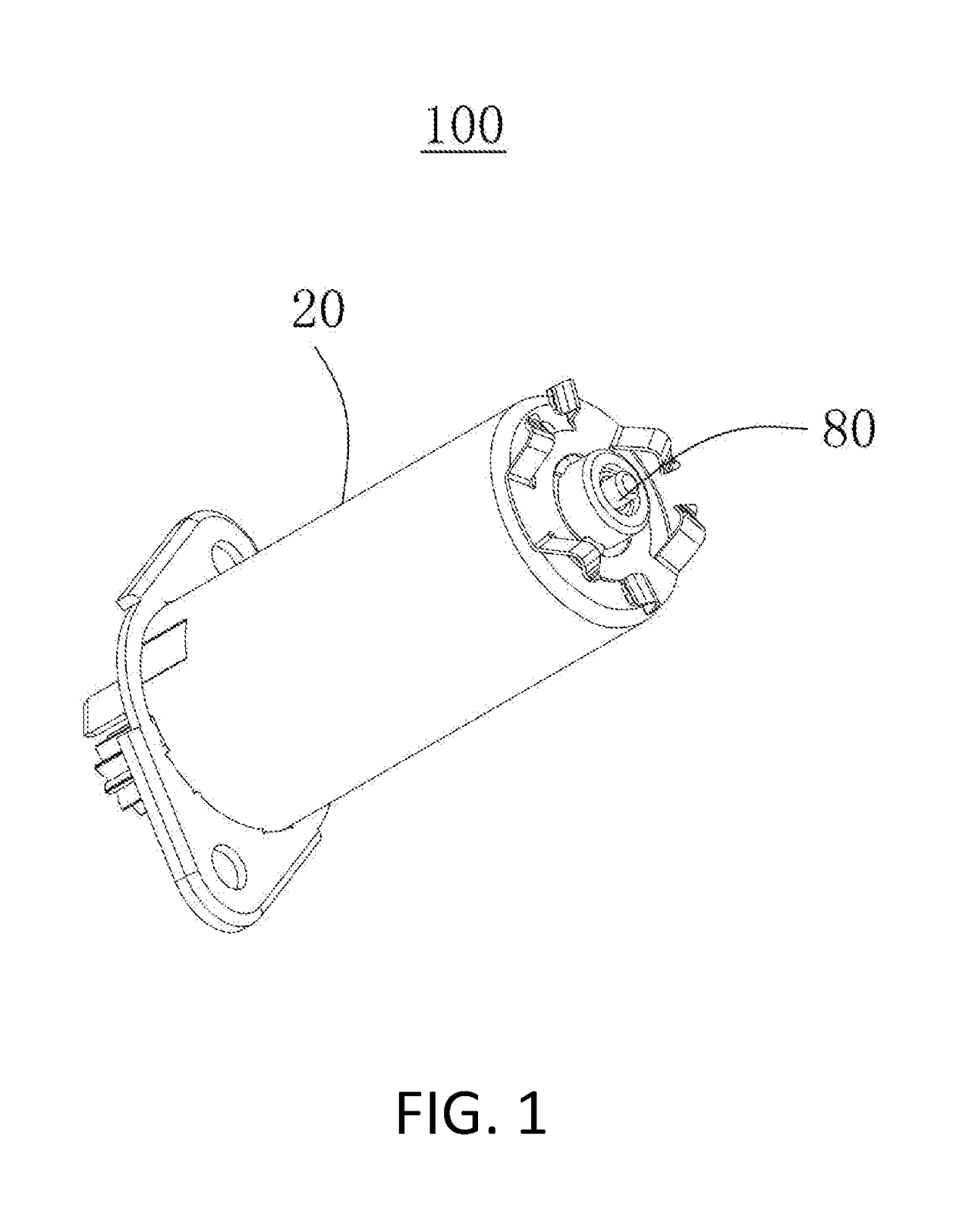
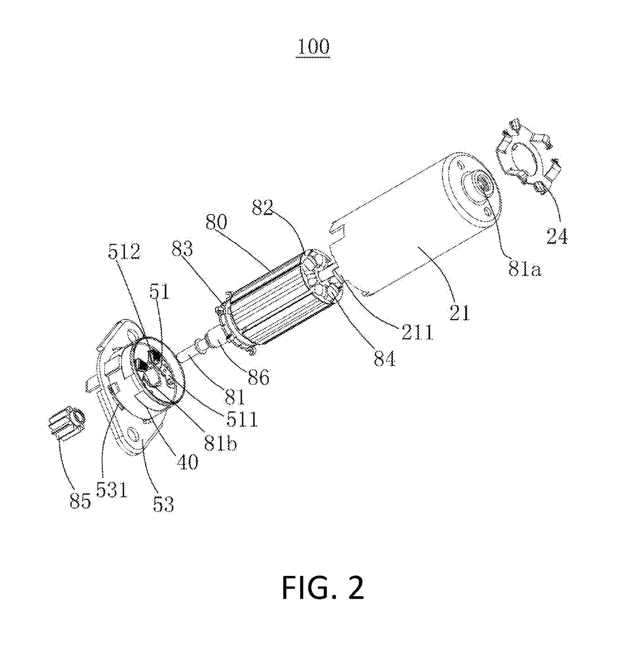
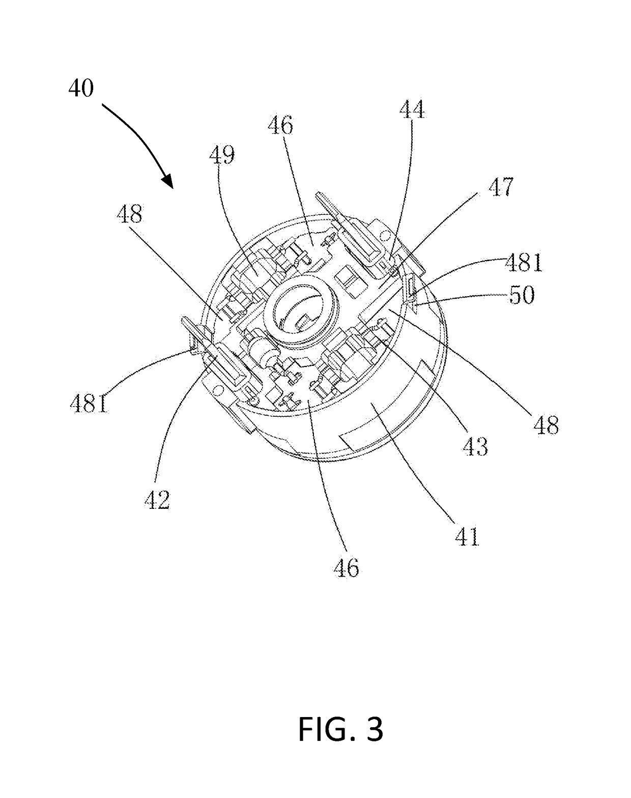
[0024]The subject matter will be described in conjunction with the accompanying drawings and the preferred embodiments. The described embodiments are only a few and not all of the embodiments of the present disclosure. All other embodiments obtained by those ordinarily skilled in the art based on the embodiments of the present disclosure without any creative efforts fall within the protection scope of the present disclosure. It is to be understood that, the drawings are provided for reference only and are not intended to be limiting of the invention. The dimensions shown in the drawings are only for convenience of illustration and are not intended to be limiting.

[0025]It should be noted that when a component is considered to be “connected” to another component, it can be directly connected to another component or may also have a centered component. Unless otherwise defined, all technical and scientific terms used herein have the same meaning as commonly understood by those ordinaril...


PUM


Abstract

An electric motor, an end cap thereof and a manufacturing method of the end cap are provided. The end cap includes an insulating body and a filter circuit board mounted to the insulating body. The filter circuit board includes at least two power conductors for receiving an external power source, an insulating support frame integral with the at least two power conductors, and at least one filter element. One end of the at least one filter element is connected to a corresponding power conductor, and the other end of the at least one filter element is grounded.

Description

CROSS REFERENCE TO RELATED APPLICATIONS[0001]This non-provisional patent application claims priority under 35 U.S.C. § 119(a) from Patent Application No. 201710563187.X filed in The People's Republic of China on Jul. 11, 2017.FIELD OF THE DISCLOSURE[0002]This present disclosure relates to an electric motor, an end cap thereof and a manufacturing method of the end cap.BACKGROUND OF THE DISCLOSURE[0003]The end caps of current electric motors are substantially cylindrical, mounted with power terminals and filter elements, such as capacitors, inductors, and resistors. Typically, the end cap has a plurality of mounting grooves and holes for mounting the filter elements and the pins thereof. When mounting the filter elements, it is necessary to manually bend the pins of the filter element into corresponding shapes to pass through the corresponding mounting holes, and then place the filter elements in the corresponding mounting grooves. The pins of the filter elements are manually soldered...

Claims


Application Information

Patent Timeline
Patent Type & Authority Applications(United States)
IPC IPC(8): H02K5/08H01R39/38H02K5/14
CPCH02K5/08H02K5/148H01R39/38H02K11/30H02K11/40H02K5/145H02K5/225H02K13/10H02K15/14H02K2211/03H02K23/66H02K5/146H02K11/026H02K5/14
Inventor YEUNG, YUKWAILAU, CHINGSIKZHOU, DAWEITAM, SIUKINFU, TAO
Owner JOHNSON ELECTRIC SA
Learn More