Wheel for a road vehicle

a technology for road vehicles and wheels, applied in the direction of magnetic circuit rotating parts, magnetic circuit shape/form/construction, transportation and packaging, etc., can solve the problems of large currents required to provide the necessary power and torque, temperature rise of electric motors and wheels, and complicated, etc., to increase the efficiency of electric motors and limit any deformation of the rim.

Active Publication Date:
View PDF15 Cites 3 Cited by
  • Summary
  • Abstract
  • Description
  • Claims
  • Application Information

AI Technical Summary

Benefits of technology

[0017]In an embodiment the rim has first and second ends along a rotation axis of the wheel, the rim support being associated with the first and second ends of the rim. Both ends of the rim are in such configuration supported, which is efficient to limit any deformation of the rim.
[0018]In an embodiment the rim support comprises first and second plates associated with the first and second ends of the rim, and the rotor being supported by and provided in between the first and second plates. The plates prove to be an efficient means for supporting the rim and to provide a support for the rotor as well. The plates very effectively pass any loads to the shaft. They can easily be configured such that they will not deform under any load.
[0019]In an embodiment the rotor comprises a magnet holding element that is supported on the rim support, the magnet holding element being manufactured from a material that is selected for its optimum magnetic flux guiding properties. Since the material of the rotor need not be selected for its mechanical strength it can be selected for optimum flux-guiding properties to increase efficiency of the electric motor.

Problems solved by technology

Further, large currents are required to provide the necessary power and torque to the motor.
This causes a temperature rise of the electric motor and wheel, and cooling is required to limit the temperature rise.
Various solutions have been proposed, but they are all quite complicated.

Method used


Image

  • Wheel for a road vehicle
  • Wheel for a road vehicle

Examples


Embodiment Construction

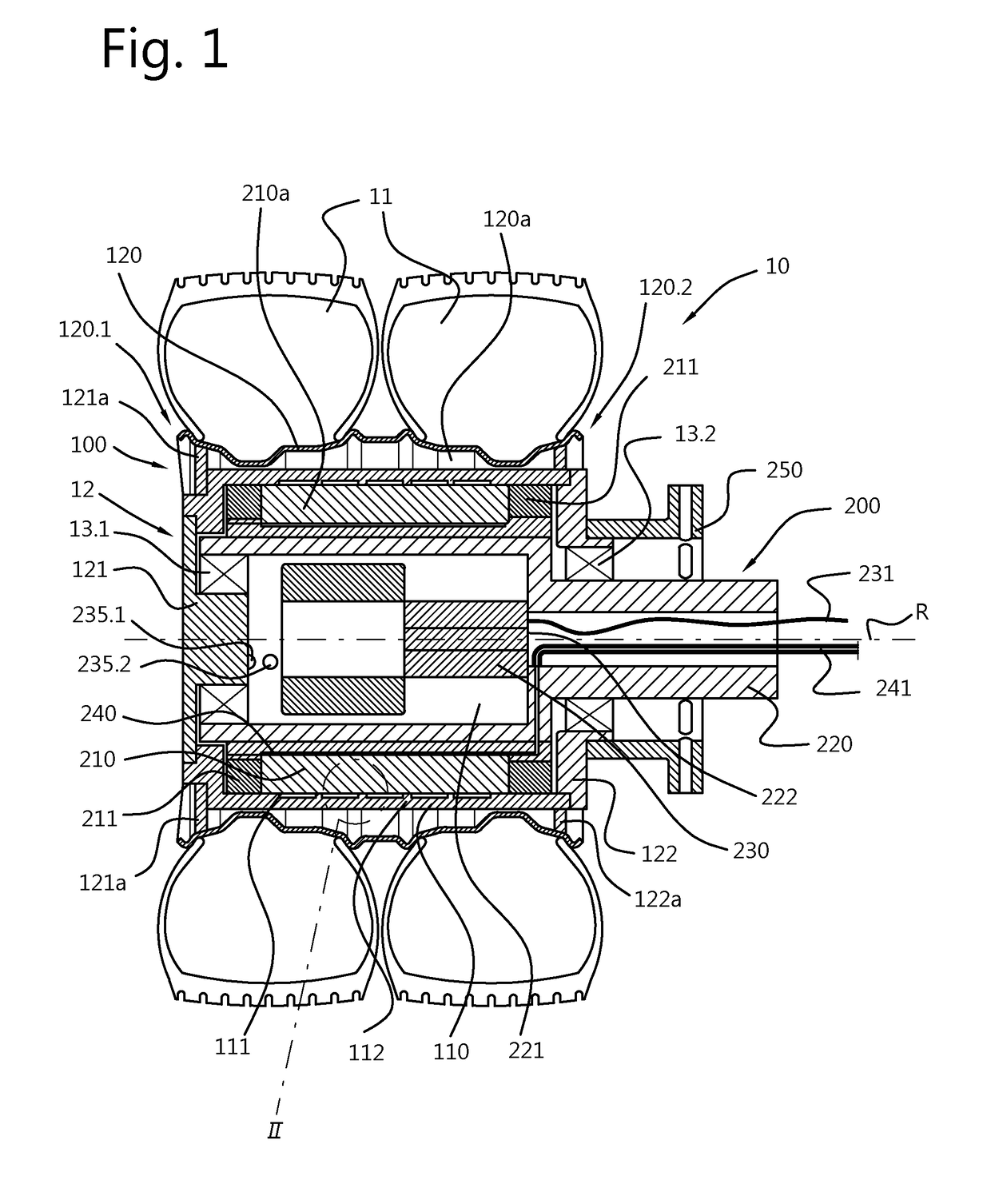
[0041]A wheel 10 for a road vehicle, such as a car, bus or truck, is shown in FIG. 1 and comprises a rotating part 100 and a static, non-rotating part 200. An electric motor 12 is arranged inside the wheel to provide for an in-wheel electric motor. Two tires 11 are mounted on a rim 120 of the wheel. In other embodiments one or more tires may be mounted on a suitable rim of the wheel, which can be standard size tires for the intended application of the wheel, such as for buses or cars. A first (front) plate 121 and a second (back) plate 122 together with their annular extensions 121a, 122a provide a rim support and are rigidly attached to the rim. The rim 120, the front and back plates 121, 122 and annular extensions 121a, 122a are rotating parts of the wheel and the rim is supported by the front and back plates and their annular extensions. The rim 120 has first and second ends 120.1, 120.2 along a rotation axis R of the wheel. The first / front plate 121 is associated with the first ...


PUM


Abstract

Disclosed is road vehicle wheel with an in-wheel electric motor that includes a rim configured for mounting at least one tire on the rim; a rim support configured for supporting the rim on a non-rotating wheel part to allow rotation of the rim with respect to the non-rotating wheel part; a stator of the in-wheel electric motor, the stator including electromagnets and being supported on the non-rotating wheel part; and a rotor of the in-wheel electric motor, the rotor including permanent magnets and being supported on the rim support such that any forces exerted on the rim do not act on the rotor. The rim is supported such that any forces exerted on the rim are directly born by the rim support and is not in direct contact with the rotor.

Description

FIELD OF THE INVENTION[0001]a road vehicle wheel with an in-wheel electric motor, the wheel comprising a rim and a rotor with permanent magnets and a stator with electromagnets.BACKGROUND OF THE INVENTION[0002]Wheels driven by an electric motor are known. The electric motor can be provided in the car and drive the axis of the wheel to rotate the wheel. This requires the electric motor to be located in the car. Another possibility is to position the electric motor in the wheel itself. Such wheels having an in-wheel electric motor are known as well. Part of the electric motor is generally coupled to the rim of the wheel, the rim carrying the tire of the wheel. Another part of the in-wheel electric motor is generally positioned centrally in the wheel and will constitute a non-rotating part of the wheel. The non-rotating part of the electric motor and part of the electric motor coupled to the rim are generally referred to as stator and rotor, respectively. The interaction between rotor ...

Claims


Application Information

Patent Timeline
Patent Type & Authority Applications(United States)
IPC IPC(8): B60K7/00H02K11/33H02K21/22H02K9/19B60B7/06
CPCB60K7/0007H02K11/33H02K21/22H02K9/19B60B7/063B60K2007/0038H02K1/30H02K7/14
Inventor VAN DER WAL, REINHARD PETERSEVENTER, TIMOTHY
Why Eureka
Try Eureka