System for combustion of fuel to provide high efficiency, low pollution energy

a technology of combustion system and fuel, which is applied in the direction of combustion type, combustion using catalytic material, emission prevention, etc., can solve the problems of high cost, high cost, and potential danger of the principal method being considered, and achieves the effects of reducing co2 and other air pollution levels, reducing carbon dioxide, and increasing thermal efficiency

Active Publication Date: 2019-01-24
TAPLIN JR HARRY R
View PDF0 Cites 3 Cited by
  • Summary
  • Abstract
  • Description
  • Claims
  • Application Information

AI Technical Summary

Benefits of technology

[0016]Set forth herein is a method for utilizing catalysts to reduce carbon dioxide and other harmful emissions generally produced in fossil fuel combustion processes. The method is directed to a controlled process which reduces CO2 and other air pollution levels and increases thermal efficiency. The method includes a process for controlling, regulating and optimizing the complex interactions in gas and plasma states of fossil fuel combustion. The methods and processes disclosed herein are unique and unobvious methods of optimizing the use of catalysis in fossil fuel combustion processes, providing for the initiating and controlling or regulating a process which results in reduced CO2 and other air pollution levels and increased thermal efficiency. As a result, CO2 and other harmful air pollutants are significantly reduced while thermal efficiencies are brought to new higher levels. The optimizing steps include not only positive methods but also steps to elimination moderators that work against the effectiveness of the processes. One aspect of these processes are interactions with chamber surface components such as boiler tube walls, cylinder confines, insulation materials exposed to combustion and the combustion gases. As a result of these controlled methods of operation, harmful air pollutants are significantly reduced while thermal efficiencies are brought to new higher levels.
[0017]One aspect of the process set forth herein is to provide a method for reducing CO2 at its source in fossil fuel combustion processes which is simple, inexpensive and can be applied worldwide in a short period of time without need for complex and expensive mechanical operations and equipment such as scrubbers, precipitators, bag houses, particulate traps and fly ash collectors, catalytic converters and complex control systems that have emerged as solutions to combustion pollution problems since the 1970's. Furthermore, the process reduces energy expenses for all users of coal, oil and gas including electrical generation. Still further, the process is useful for combating the specter of global warming and reducing the tremendous harm being caused by air pollution to humans, the environment, to other life forms and forests while providing cheaper energy as an incentive to invest in this technology for the common good. Further, the process increases profits and lowers energy bills while reducing harmful pollution, especially CO2 suspected to be a cause or global warming. Still further, while the process is reducing CO2 it also produces oxygen which is a further beneficial result.

Problems solved by technology

It is generally agreed that combustion processes are extremely complex with many reactions and processes occurring over very short time spans measured in micro seconds.
However, the catalysts of identified herein are not commonly used.
The principal method being considered, namely carbon capture and storage (CCS), is a very expensive and a potentially dangerous process.
These and other system costs are estimated to increase the cost of energy from a new power plant with CCS by 21-91%.
Applying the CCS technology to preexisting plants or plants far from a storage location is more expensive.
A prominent government official with responsibilities to solve this problem has termed this challenge a nightmare.
Carbon dioxide under high pressures used in this process are quite slippery and leaks that have occurred have been lethal to animals and humans.
Some other solutions being investigated include deep ocean storage with the risk of greatly increasing the problem of ocean acidification, dead zones, reef destruction and sea life kill-off in a manner similar to toxic and acid laden air pollution.
Although the processes involved in CCS have been demonstrated in some isolated industrial applications, no commercial scale projects which integrate these processes exist, and therefore the costs are uncertain.
However, this procedure it is still in the experimental and development stage.
Cost and capacity are a challenge and it does not seem to be scalable to a sufficient level to turn around the current trends in carbon dioxide accumulation in the atmosphere.

Method used


Image

  • System for combustion of fuel to provide high efficiency, low pollution energy
  • System for combustion of fuel to provide high efficiency, low pollution energy
  • System for combustion of fuel to provide high efficiency, low pollution energy

Examples


example 1

[0116]Two vehicles, one a diesel powered farm tractor and the second a gasoline powered pick-up truck were tested using the process. For the gasoline powered Dodge pickup truck, a mix of 3.3 milliliters per gallon of gasoline was used. The isopropyl additive mix, contained 30 grams of lithium nitrate per gallon. This was poured straight into the fuel tank. The gas powered light truck first produced a drop in CO2 of 52%, and then it went to a 93% after accumulating about 50 road miles. The exhaust gas samples were measured near the engine exhaust before the catalytic converter. For the diesel tractor, a mix of 5 milliliters per gallon of diesel was used from the same isopropyl additive mix containing 30 grams of lithium nitrate per gallon. This was also poured straight into the fuel tank. Exhaust gas samples were drawn directly from the engine exhaust. The diesel engine's CO2 level dropped by 94% from baseline tests after catalyst treatment after running for about an hour. Gas sample...

example 2

[0117]A 5 month test was conducted on a natural gas fired boiler rated at 12 million BTUs per hour which providing steam for utilities service at a UC Irvine. The lithium nitrate in this case was mixed in water and fed into the gas burner using a humidification system with an average concentration of the lithium nitrate to the average natural gas burn of 5 parts per million. A series of 7 analysis towards the end of this testing period indicated CO2 averaging 73% below theoretical. The plant installed oxygen analyzer; a portable Combustion Analyzer and a set of absorption chemical CO2 instruments were used for the test. In one case, at a constant 2.2% oxygen reading, the theoretical % CO2 for natural gas should have had a corresponding value of 12%, but the actual value of CO2 averaged a much lower 3.13% indicating the drop in CO2 of 73%.

example 3

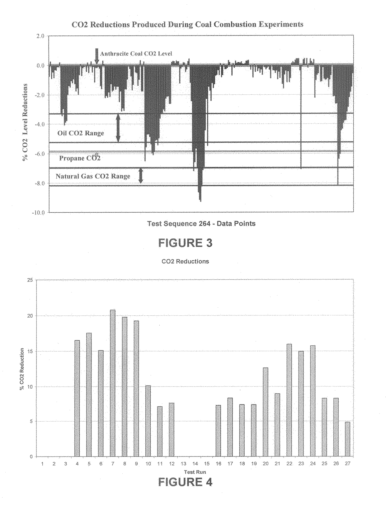
[0118]Drop-tube combustion testing of coal samples using a target concentration for the catalyst of 5 parts per million using a water mix dripped coal samples provided the follow results:[0119]Carbon Dioxide (CO2) reductions of 30% and 53%[0120]Nitrous Oxide (NO) reductions of 58% and 77%[0121]Sulfur Oxide (SOx) reductions of 8% and 40%


PUM


Abstract

An afterburner system and method for reducing the CO2 and other pollutants produced by the combustion of a fuel in a combustion chamber while maintaining or increasing the efficiency of said combustion includes feeding a catalyst, preferably lithium and/or boron to the afterburner, or a preconditioning afterburner, along with the exhaust from the combustion chamber. The presence of the catalyst in the after burner results in further reduction of pollutants generated by the combustion in the combustion chamber.

Description

[0001]This application is a Continuation-in-Part of Ser. No. 15 / 633,664 filed Jun. 26, 2017, now U.S. Pat. No. 10,082,288 issued Sep. 25, 2018, which is a Divisional of U.S. application Ser. No. 13 / 175,761 filed Jul. 1, 2011, now U.S. Pat. No. 9,702,546, issued Jul. 11, 2017, which is a Divisional of U.S. application Ser. No. 12 / 914,921 filed Oct. 28, 2010 claiming benefit of U.S. Provisional Application 61 / 361,323 filed Jul. 2, 2010.FIELD OF THE INVENTION[0002]Processes utilizing catalysts to reduce carbon dioxide and other harmful emissions from fossil fuel combustion which increase heat and energy production, improve efficiencies of engines, boilers and turbines and increase oxygen in the exhaust streams from fossil fuel combustion processes are described.[0003]While the invention described herein is applicable to all fuel burning devices including, but not limited to, burners, combustion chambers and engines, in a particular embodiment an engine with reduced carbon oxide emissio...

Claims


Application Information

Patent Timeline
Patent Type & Authority Applications(United States)
IPC IPC(8): F23C13/00F23N5/00F23N1/08F23N5/02
CPCF23J2219/10F23J2215/50F23N2037/12Y02E20/328F23N5/003F23N1/082F23C13/00F23N5/022F23C13/08F23N2237/12Y02E20/32
Inventor TAPLIN, JR., HARRY R.
Owner TAPLIN JR HARRY R
Why Eureka
Try Eureka