Integrated photonic microwave transceiver system

a photonic microwave and transceiver technology, applied in the field of photonic systems, can solve the problems of system limitations and extremely difficult conventional techniques

Active Publication Date: 2019-01-24
IMRA AMERICA
View PDF2 Cites 30 Cited by
  • Summary
  • Abstract
  • Description
  • Claims
  • Application Information

AI Technical Summary

Benefits of technology

[0011]In an example embodiment in which the microwave photonics system is configured as a broadband spectral analyzer / receiver, the comb spacings of the combs OFC1 (f1) and OFC2 (f2) are separated at a predetermined difference Δf=|f1−f2 |. The broadband input RF signal is modulated to all optical comb lines of OFC1 through the EOMm. The mismatch between the comb spacings of the two OFCs, in combination with the optical wavelength de-multiplexing, spectrally slices the input signal into N segments at a separation of Δf, where N is the total number of WDM channels. RF down-conversion is achieved by optical heterodyning of the segmented EOC1 sidebands and the comb lines of OFC2 at the OECs of the N WDM channels, enabling the detection of broadband microwave signals with low-bandwidth ADCs. In the case when the bandwidth (denoted BW) of the detection module is smaller than to Δf (e.g., Δf˜k·BW, k is an integer), time-division multiplexing can be realized by programming an additional DDS with a waveform whose instantaneous frequency monotonously changes by the bandwidth BW for k steps. When such a waveform is used to drive the SSCSM in the OFS, comb lines of OFC2 are shifted periodically following the driving signal generated by the DDS. In this way, each WDM channel can be fully covered and analyzed in a sequential way.

Problems solved by technology

Such systems can have limitations.
With the rapid development of broadband radio frequency technology comes the need for a compact transceiver system that generates multiple coherent microwave carriers for independent channel control and analyzes broadband input signals with fast acquisition speed, which can be extremely difficult for conventional techniques.

Method used


Image

  • Integrated photonic microwave transceiver system
  • Integrated photonic microwave transceiver system
  • Integrated photonic microwave transceiver system

Examples


Embodiment Construction

Overview

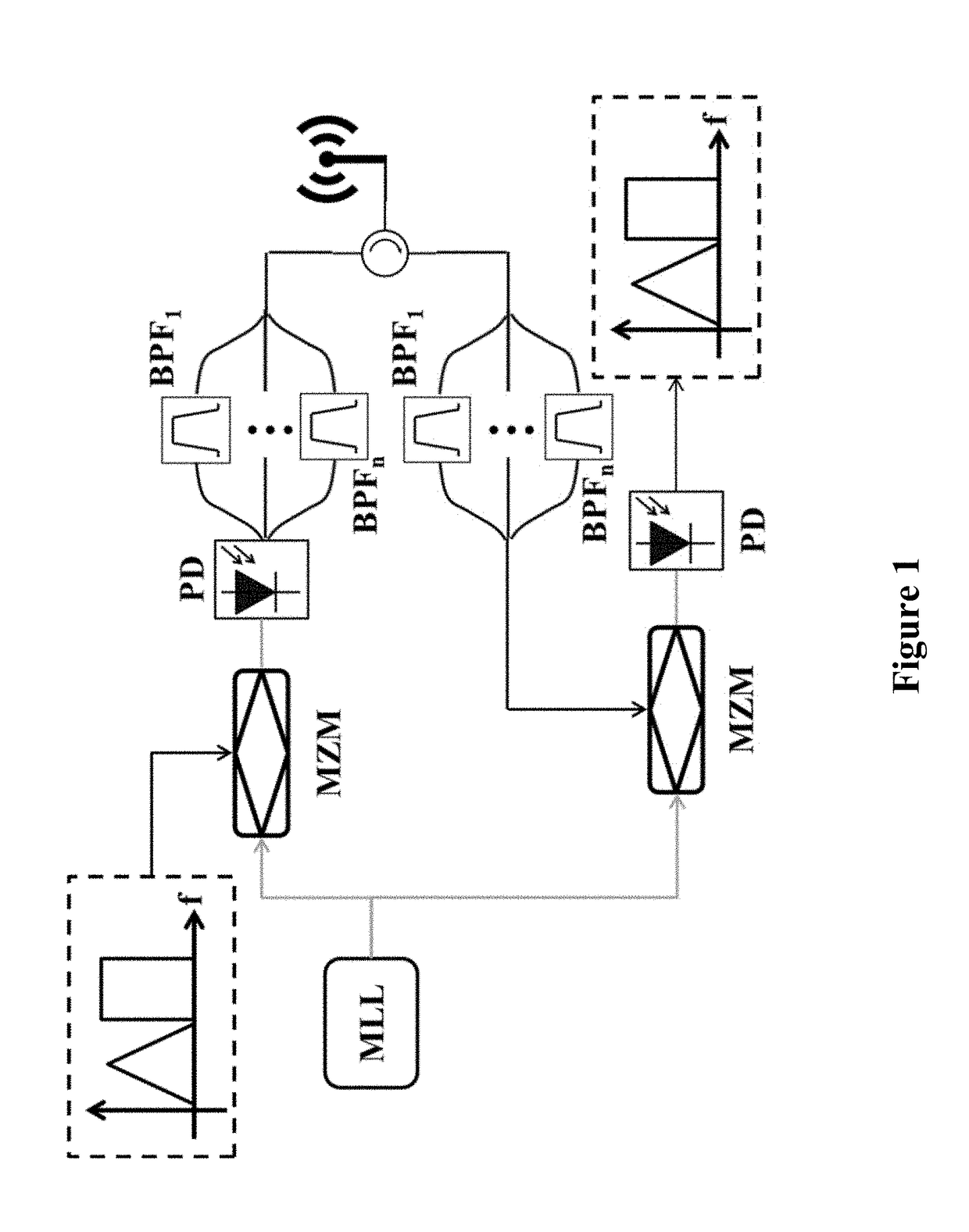
[0029]FIG. 1 schematically illustrates an embodiment of a photonic microwave transceiver based on F. Laghezza and et al., “Photonics-Assisted Multiband RF Transceiver for Wireless Communications,” J. Lightwave Technol. 32, 2896-2904 (2014). On the transmitter end, the input radio frequency (RF) information is modulated into the optical domain by a Mach-Zehnder modulator (MZM) at the sidebands of each optical carrier of an optical source—a mode locked laser (MLL). Once this optical signal is transformed back to the RF domain through an optical-to-electrical convertor (OEC), for example a photodetector (PD), the sideband of a particular comb line heterodynes with its neighboring comb lines, effectively replicating the input RF information to multiple RF carrier frequencies, whose separation equals the repetition rate of the MLL. The output of the photodetector is split into multiple parts, each with an RF bandpass filter (BPF) to select a desired segment of the input RF inform...


PUM

PropertyMeasurementUnit
carrier frequencyaaaaaaaaaa
frequencyaaaaaaaaaa
frequencyaaaaaaaaaa

Abstract

Examples of systems and methods for integrated photonic broadband microwave transceivers are disclosed based on integrated coherent dual optical frequency combs. In some cases, when the system is configured as a transmitter, multiple radio frequency (RF) carriers can be generated, which can either be encoded independently, or used for broadcasting the same information into different bands. In some cases, when the system is configured as a receiver, the spectrum of the input signal can be sliced into several spectral segments for low-bandwidth detection and analysis. In some systems, the optics-related functionalities can be achieved via integrated optic technology, for example based on silicon photonics, providing tremendous possibilities for mass-production with significantly reduced system footprint.

Description

CROSS-REFERENCE TO RELATED APPLICATIONS[0001]This application claims the benefit of priority to U.S. Provisional Application No. 62 / 575,470, filed Jul. 21, 2017, entitled INTEGRATED PHOTONIC MICROWAVE TRANSCEIVER SYSTEM, and to U.S. Provisional Patent Application No. 62 / 583,963, filed Nov. 9, 2017, entitled INTEGRATED PHOTONIC MICROWAVE TRANSCEIVER SYSTEM, each of which is hereby incorporated by reference herein in its entirety.BACKGROUNDField[0002]The present disclosure relates generally to photonics systems and more particularly to an integrated microwave photonic transceiver system implementing coherent dual optical frequency combs and optical wavelength-division multiplexing.Description of the Related Art[0003]Radio frequency (RF) signal analyzers utilizing photonic channelization based on wavelength-division-multiplexing (WDM) have been developed. Time-division-multiplexing (TDM)-based microwave channelizers have also been developed. Such systems can have limitations.SUMMARY[00...

Claims


Application Information

Patent Timeline
Patent Type & Authority Applications(United States)
IPC IPC(8): H04B10/50H04J14/02H04B10/548G02F3/00
CPCH04B10/505H04J14/02H04B10/548G02F3/00G02F2203/56
Inventor KUSE, NAOYAROLLAND, ANTOINE JEAN GILBERTLI, YIHANFERMANN, MARTIN E.
Owner IMRA AMERICA
Why Eureka
Try Eureka