
System and method for radio cell synchronization

a radio cell and radio synchronization technology, applied in digital transmission, transmission path division, electrical equipment, etc., can solve the problems of ue power consumption, cfo, ue power consumption, etc., and achieve the effect of reducing the power consumption of the ue and cfo

Active Publication Date: 2019-01-24
CEVA D S P LTD
View PDF4 Cites 8 Cited by
  • Summary
  • Abstract
  • Description
  • Claims
  • Application Information

AI Technical Summary

Benefits of technology

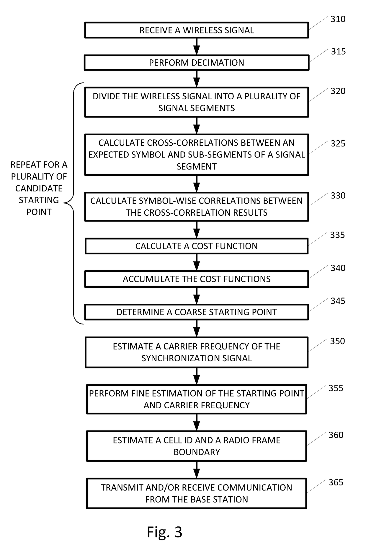
This patent provides a method and system for synchronizing wireless signals that include multiple synchronization signals. The method involves dividing the signal into multiple segments, calculating symbol-length cross-correlations between expected symbols and the pattern of sub-segments in the wireless signal, and accumulating these correlations until a predetermined condition is met. The accumulated cost function is then used to select the synchronization point. This method helps to accurately synchronize signals even in the presence of multiple synchronization signals. The system includes a decimation step to improve the efficiency of the synchronization process. The technique is particularly useful for wireless signals that include NPSS symbols.

Problems solved by technology

Such low cost oscillators may cause an initial carrier frequency offset (CFO) due to limited stability of up to 20 parts per million (ppm).
One major contributor to the UE power consumption is the radio frequency (RF) transceiver.
Reduced synchronization time results in shorter “RF-ON” period and therefore lowers the power consumption of the UE considerably.

Method used


Image

  • System and method for radio cell synchronization
  • System and method for radio cell synchronization
  • System and method for radio cell synchronization

Examples


Embodiment Construction

[0026]In the following description, various aspects of the present invention will be described. For purposes of explanation, specific configurations and details are set forth in order to provide a thorough understanding of the present invention. However, it will also be apparent to one skilled in the art that the present invention may be practiced without the specific details presented herein. Furthermore, well known features may be omitted or simplified in order not to obscure the present invention.

[0027]Unless specifically stated otherwise, as apparent from the following discussions, it is appreciated that throughout the specification discussions utilizing terms such as “processing,”“computing,”“calculating,”“determining,” or the like, refer to the action and / or processes of a computer or computing system, or similar electronic computing device, that manipulates and / or transforms data represented as physical, such as electronic, quantities within the computing system's registers a...


PUM


Abstract

A system and method for cell synchronization suitable for a wireless signal including substantially identical synchronization signals that repeat in predetermined time intervals, the synchronization signals including a plurality of substantially identical symbols. For a plurality of candidate synchronization points: dividing the wireless signal into a plurality of signal segments, each equal or longer than the time interval, and each including a plurality of sub-segments having substantially same length as the symbol; performing symbol-length cross-correlations between an expected symbol and the sub-segments; performing segmented symbol-wise correlations between the cross-correlation results; calculating a cost function based on the results of the symbol-wise correlations; accumulating the cost functions across a plurality of signal segments; and selecting a coarse synchronization point from the plurality of candidate synchronization points based on the accumulated cost function; Estimating synchronization parameters e.g. time and frequency offset based on the selected synchronization point.

Description

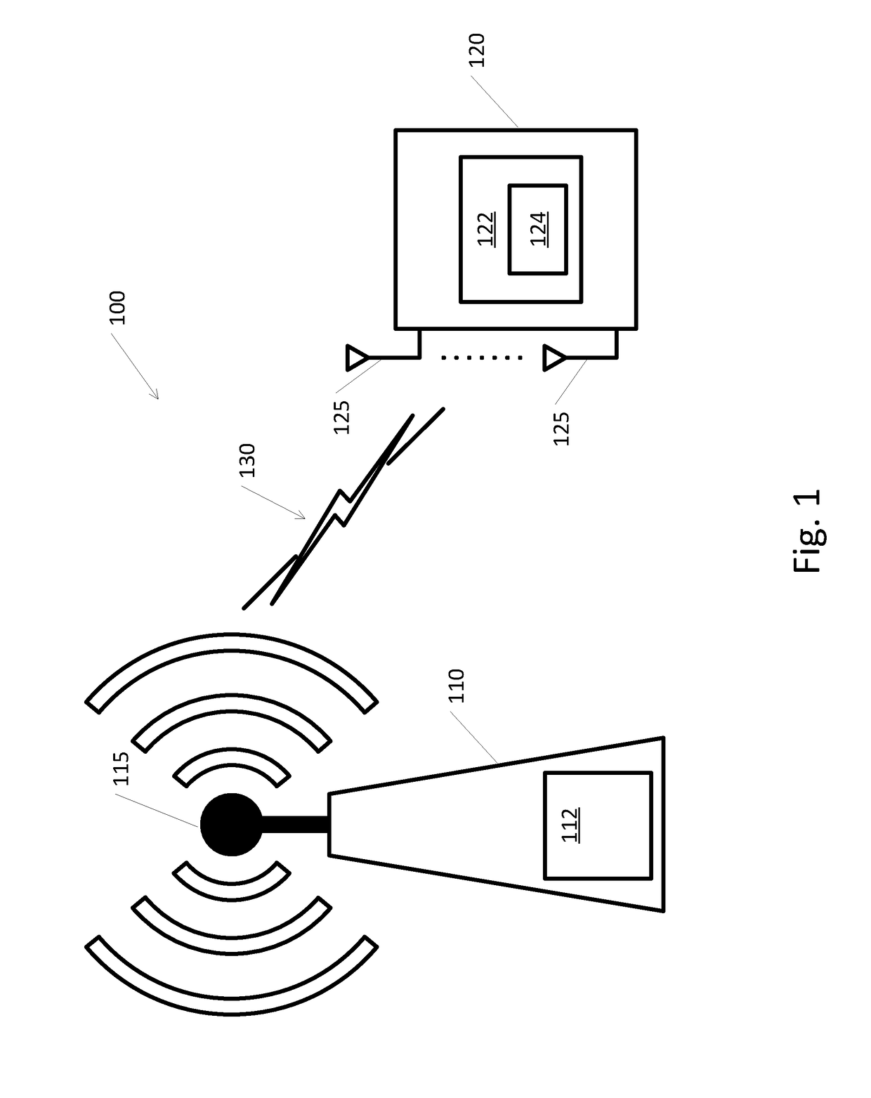
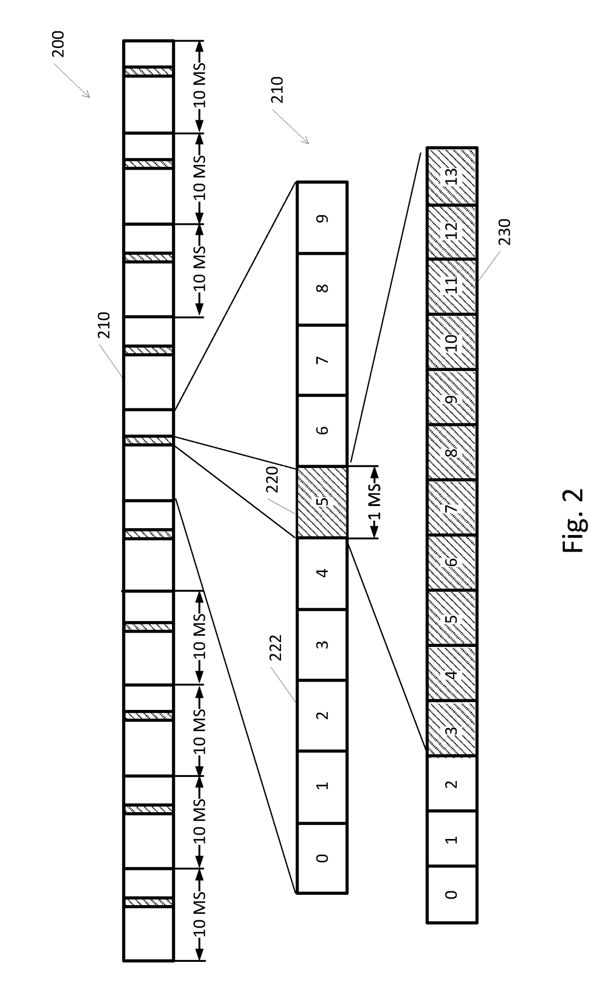
FIELD OF THE INVENTION[0001]The present invention relates generally to the field of radio communication cell synchronization, for example to cell synchronization in narrowband Internet of things (NB-IoT) radio technology standard.BACKGROUND[0002]Narrow-band internet-of-things (NB-IoT) is a Low Power Wide Area connectivity standard defined initially in 3GPP Release for the IoT market. NB-IoT is intended to be used for ultra-low cost user equipment (UE) devices, which are often equipped with low-cost oscillators. Such low cost oscillators may cause an initial carrier frequency offset (CFO) due to limited stability of up to 20 parts per million (ppm). IoT UE is expected to be dormant most of the time. When powered on, the UE needs to correct for these frequency offsets. Thus, the UEs need to perform time and frequency synchronization with the base station (eNodeB) in order to transmit and receive data. Synchronization may include aligning with the frequency of the base station, e.g., t...

Claims


Application Information

Patent Timeline
IPC IPC(8): H04W56/00H04L5/00H04L7/00
CPCH04W56/001H04W56/0055H04W88/08H04L7/007H04W88/02H04L5/0007H04W56/00
Inventor ISAACS, OMRIKAPLAN, ZEEVSHALEV, TAL
Owner CEVA D S P LTD
Learn More