Light outpost positioning

a technology for positioning lights and outposts, applied in the direction of electroluminescent light sources, lighting and heating apparatuses, electric lighting sources, etc., can solve the problems of cumbersome repositioning of light output 60/b> to a desired location and unsatisfactory user experience, and achieve the effect of convenient installation of computer program codes and intuitive user experien

Active Publication Date: 2019-01-24
SIGNIFY HLDG BV
View PDF1 Cites 9 Cited by
  • Summary
  • Abstract
  • Description
  • Claims
  • Application Information

AI Technical Summary

Benefits of technology

[0026]The method may further comprise determining a tilt angle of the luminaire relative to a surface onto which the light output is projected, wherein converting the light output positioning instruction further comprises scaling the directional information based on the determined tilt angle. Such a tilt angle for example may be determined by user calibration and has the advantage that such scaling based on the tilt angle information can ensure that repositioning of a light output projected under an angle onto a surface such as a wall can be performed in a uniform manner, i.e. resulting in equal movements of the light output regardless of the direction in which the light output is repositioned. Such a tilt angle information may further be used to provide the luminaire with spot size adjustment information in the light output positioning instruction, which spot size adjustment information is a function of the direction in which the light output is intended to be oriented, e.g. repositioned; for example, where such an (re)orientation direction increases the tilt angle, the spot size adjustment information may cause the luminaire to reduce the size of the light output produced in order for the project light output to maintain its original size.
[0027]According to another aspect, there is provided a computer program product comprising a computer readable storage medium having computer readable program instructions embodied therewith for, when executed on a processor of a user interface device for controlling a luminaire adapted to generate a light output in a controllable direction, cause the processor to implement the method of any of the embodiments described in this application. Such a computer program product for example may facilitate the installation of computer program code comprising the computer readable program instructions on any device suitable to operate as a user interface device for controlling a luminaire adapted to generate a light output in a controllable direction, e.g. a dedicated user interface device or a general purpose computing device such as a personal computer, laptop computer, tablet computer, personal digital assistant, mobile phone, e.g. a smart phone, and so on.
[0028]According to yet another aspect, there is provided a user interface device for controlling a luminaire adapted to generate a light output in a controllable direction, the user interface device comprising a processor communicatively coupled to a user interface; a data storage device embodying the computer program product according to any embodiment as described in this application and a wireless communication module, wherein the processor is adapted to execute the computer readable program instructions of the computer program product and to send a light output positioning instruction received on the user interface to the luminaire with the wireless communication module. Such a user interface device, e.g. a dedicated user interface device or a general purpose computing device such as a personal computer, laptop computer, tablet computer, personal digital assistant, mobile phone, e.g. a smart phone, and so on, facilitates an intuitive user experience when controlling the light output position generated with the luminaire.

Problems solved by technology

A problem commonly encountered with such user interface devices is that the direction in which the icon 21 is moved does not correspond to the direction in which the light output 60 is moved by the luminaire receiving the light output position adjustment instruction corresponding to the directional information provided by the user to the user interface device 10 through its user interface 20, as indicated by the block arrows in FIG. 1.
This makes repositioning the light output 60 to a desired location rather cumbersome, as the user has to figure out how to relate the light output the location direction provided to the user interface 20 to the actual light output relocation direction generated by the luminaire in response to the relocation instruction received from the user interface device.
This therefore leads to an unsatisfactory user experience.

Method used


Image

  • Light outpost positioning
  • Light outpost positioning
  • Light outpost positioning

Examples


Embodiment Construction

[0041]It should be understood that the Figures are merely schematic and are not drawn to scale. It should also be understood that the same reference numerals are used throughout the Figures to indicate the same or similar parts.

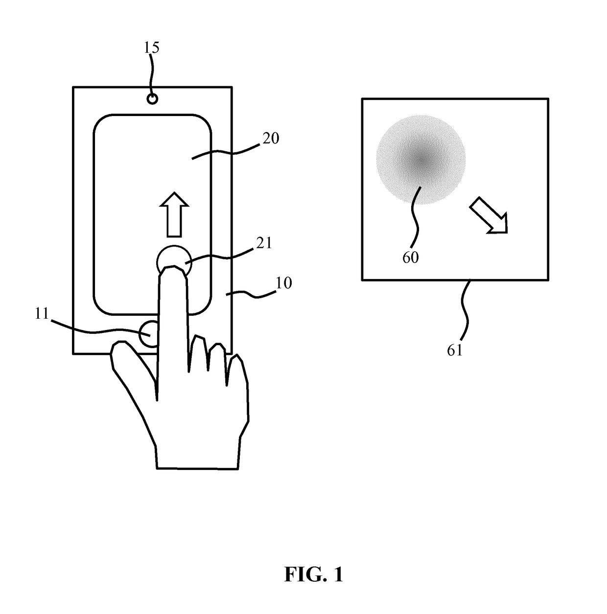
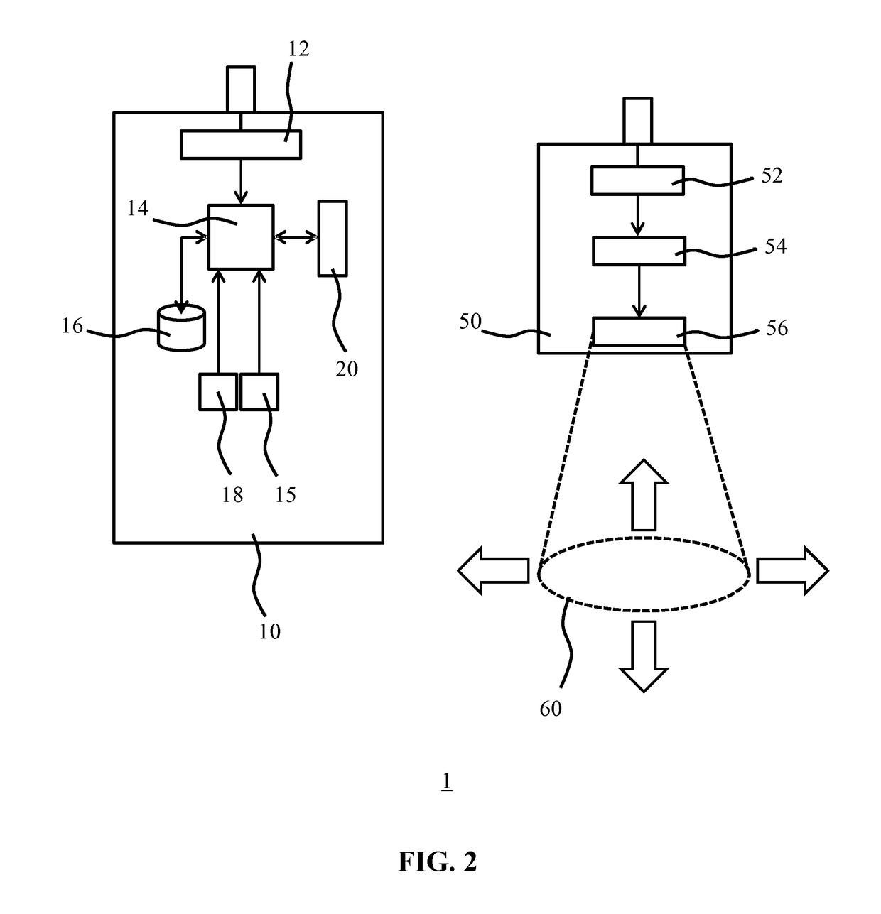
[0042]In the context of the present application, where reference is made to the orientation of a luminaire, this may mean the orientation from which the luminaire generates a light output onto a surface in a particular direction. For example, such an orientation may be defined in terms of a light exit surface of the luminaire, such that the direction in which a spot is generated may be derived from orientation information indicative of the luminaire orientation. The orientation of a luminaire may be defined in terms of an orientation in any suitable coordinate system, and may be defined in terms of an orientation relative to the Earth's magnetic poles or as a rotational orientation about a nadir axis. In some embodiments, the luminaire orientation may be furt...


PUM


Abstract

A method (200, 300) of controlling a luminaire (50) adapted to generate a light output (60) in a controllable direction with a user interface device (10) is disclosed. The method comprises determining (207) a relative orientation of the user interface device to the luminaire; receiving (219) a light output positioning instruction on a user interface (20) of the user interface device, said light output positioning instruction including directional information for the positioning of the light output in a specified location; converting (221) the light output positioning instruction by transforming the directional information based on the determined relative orientation; and transmitting (223) the converted light output positioning instruction to the luminaire. A computer program product, user interface device and lighting system employing this method are also disclosed.

Description

FIELD OF THE INVENTION[0001]The present invention relates to a method of controlling a luminaire adapted to generate a light output in a controllable direction with a user interface device.[0002]The present invention further relates to a computer program product for implementing such a method on a user interface device.[0003]The present invention yet further relates to a user interface device adapted to implement such a method.[0004]The present invention even further relates to a lighting arrangement including such a user interface device and a luminaire adapted to generate a light output in a controllable direction.BACKGROUND OF THE INVENTION[0005]With the advent of solid state lighting solutions, e.g. LEDs, a trend towards generating dynamic lighting effects has emerged in order to increase the appeal of such lighting effects. For example, WO 2012 / 113036 A1 discloses a system for providing illumination. The system comprises a source of electromagnetic radiation, a user interface t...

Claims


Application Information

Patent Timeline
Patent Type & Authority Applications(United States)
IPC IPC(8): H05B33/08H05B37/02F21V23/04H05B44/00
CPCH05B33/0842H05B37/0272F21V23/0435H05B47/19H05B47/195H05B45/00
Inventor CLOUT, RAMON ANTOINE WIROENGELEN, DIRK VALENTINUS RENEALIAKSEYEU, DZMITRY VIKTOROVICHVAN DE SLUIS, BARTEL MARINUSVAN GHELUWE, JOCHEN RENAATNEWTON, PHILIP STEVEN
Owner SIGNIFY HLDG BV
Why Eureka
Try Eureka