
A current measuring device protected against electrical surges when opening the circuit

a current measuring device and circuit technology, applied in the direction of instruments, overload protection arrangements, inductances, etc., can solve the problems of electric arcs being struck at the output of the ct, or even within its windings, non-negligible risks, etc., and achieve the effect of conserving accuracy and effective protection

Active Publication Date: 2019-01-31
SAFRAN ELECTRICAL & POWER
View PDF0 Cites 2 Cited by
  • Summary
  • Abstract
  • Description
  • Claims
  • Application Information

AI Technical Summary

Benefits of technology

The invention aims to provide effective protection for operators and current measuring devices, while meeting the accuracy requirements of aircraft manufacturers.

Problems solved by technology

Nevertheless, using CTs raises a problem.
It can lead to electric arcs being struck at the output from the CT, or even within its windings.
In an airplane this can lead to non-negligible risk, since these phenomena continue to be maintained so long as they have not been detected, and they can give rise to a fire.
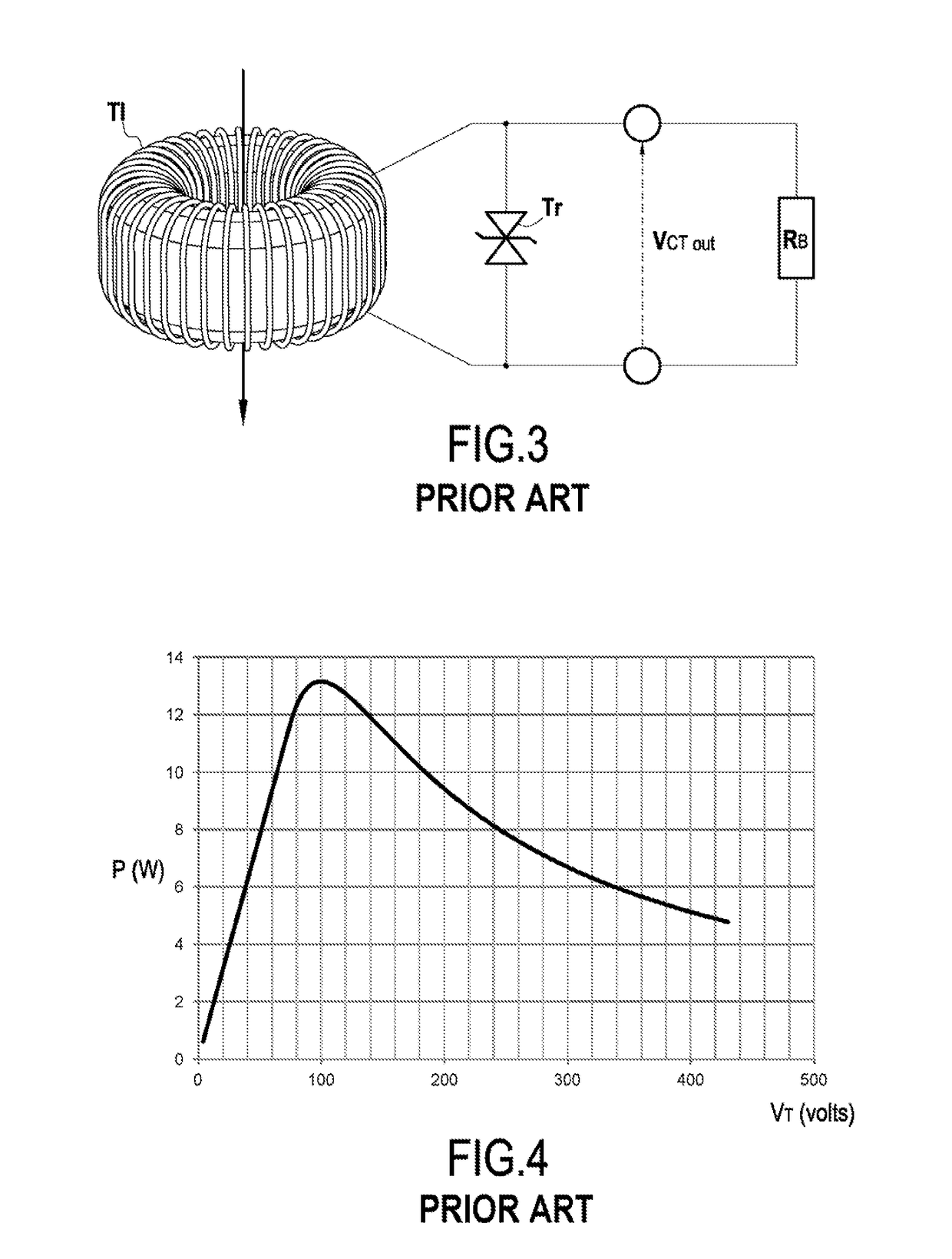
Given the very large losses for the peak-limiter type protection, a heatsink must be provided to evacuate the power dissipated by this protection, since the peak-limiter runs the risk of not withstanding the temperature.
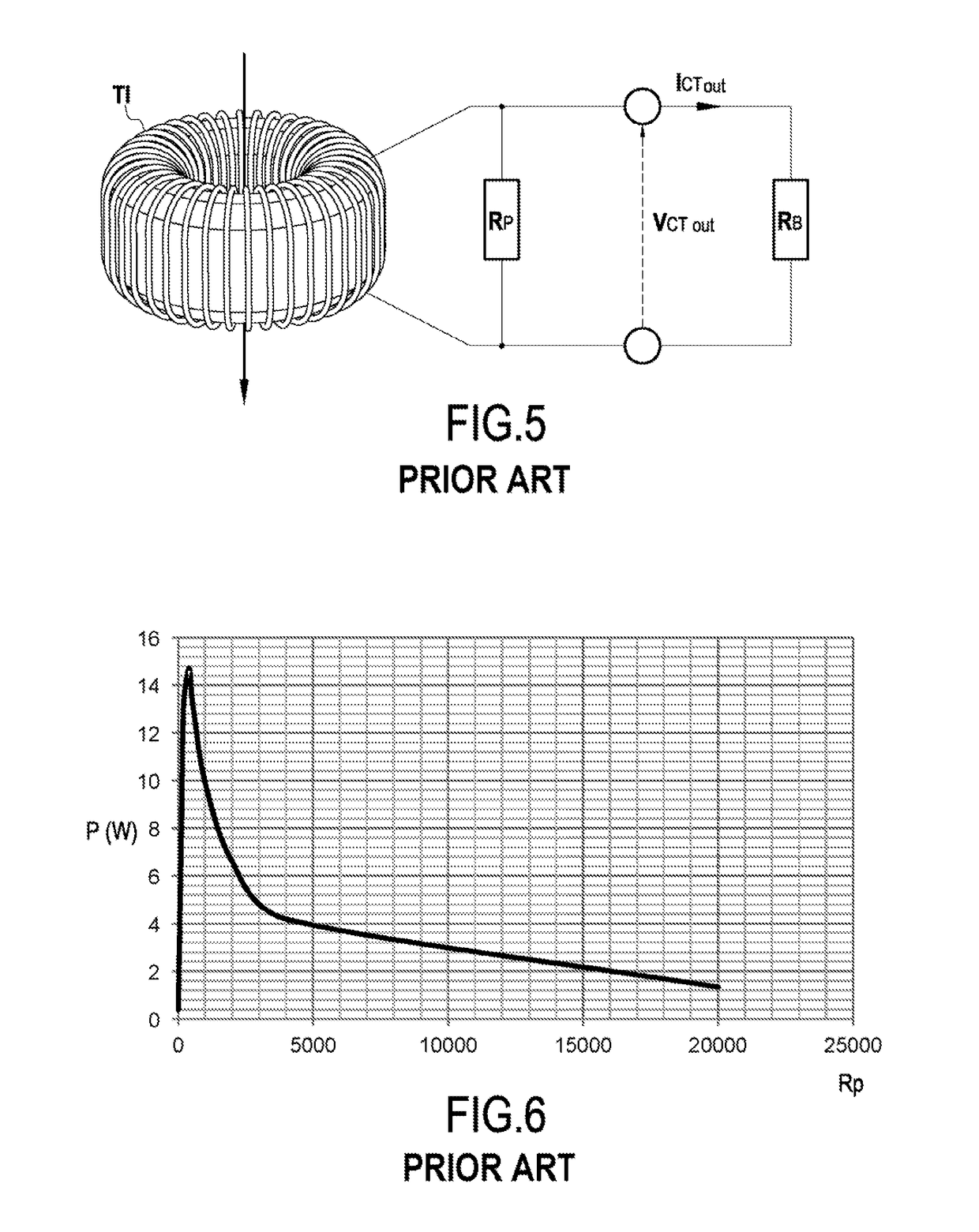
In contrast, when the resistance is very low, i.e. of the order of no more than about 100 ohms, losses are low and the output voltage is limited, but under such circumstances, accuracy is not very high.
Although RB and Rp can be accurate, Rl is subject to inaccuracy concerning knowledge about the length of the line.
The major drawback of this solution is that it is difficult to use for providing differential protection.
Other kinds of protection also exist that generally make use of active electronics, thereby reducing the overall reliability of the current measuring device including the CT.
Adding protection, such as resistances, for example, to the CT generally leads to a loss of accuracy in the final output measurement.
This loss of accuracy then gives rise to a need to raise the fault detection thresholds, in particular for differential faults.
Furthermore, such protection is generally not capable of withstanding a permanent fault.
It can thus likewise lead to overheating and starting a fire.

Method used


Image

  • A current measuring device protected against electrical surges when opening the circuit
  • A current measuring device protected against electrical surges when opening the circuit
  • A current measuring device protected against electrical surges when opening the circuit

Examples


first embodiment

[0075]In FIG. 10, there is shown an electrical circuit diagram of a current measuring device in the invention.

[0076]The current measuring device 1 comprises a first current transformer in the form of a magnetic torus 2 possessing a first number N1 of loops, i.e. of turns, and a second current transformer in the form of a magnetic torus 3 possessing a second number N2 of loops equal to the first number N1 of loops. The cores of the first magnetic torus 2 and of the second magnetic torus 3 are made of the same material and they have the same dimensions. Thus, the first and second magnetic torus 2 and 3 are identical.

[0077]The first magnetic torus 2 presents a first coupling terminal 21 and a second coupling terminal 22. The second magnetic torus 3 presents a first coupling terminal 31 and a second coupling terminal 32.

[0078]The current measuring device 1 also comprises a first connection terminal 4 and a second connection terminal 5, together with a load resistance 6 connected between...

second embodiment

[0106]FIG. 13 is a circuit diagram of an electrical circuit of a current measuring device in the invention.

[0107]Elements of the current measuring device 10 that are identical to the current measuring device 1 of the first embodiment shown in FIG. 10 are given the same numerical references.

[0108]The current measuring device 10 in the second embodiment differs from the current measuring device 1 in the second embodiment shown in FIG. 10 in that the capacitance 8 forming the current branch connection means has been replaced by a parallel circuit comprising a first branch of three diodes connected in series to conduct in a first direction and a second branch likewise comprising three diodes connected in series but to conduct in a second direction opposite to the first direction.

[0109]Since the value R of the protective resistance 7 is selected to be as close as possible to the sum of the value Rlof the line impedance 61 plus the value RB of the load resistance 6, in nominal operation o...


PUM


Abstract

A current measuring device is protected against electrical surges in the event of the device being open circuit. The device includes a first current transformer, a first connection terminal having connected thereto a first terminal of the first current transformer, a second connection terminal having connected thereto a second terminal of the first current transformer, a protective resistance having a first terminal connected to the second connection terminal, and a load resistance connected between the first and second connection terminals across the terminals of which a voltage is measured from which the current flowing in a circuit passing through the first current transformer is determined. The device also includes a second current transformer connected to the terminals of the protective resistance, and current branch connection structure connected between the first connection terminal and a second terminal of the protective resistance.

Description

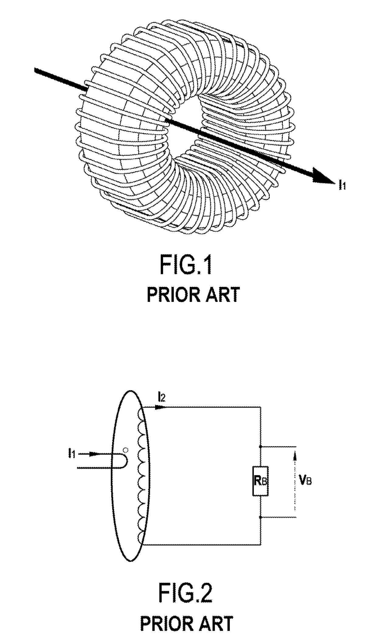
BACKGROUND OF THE INVENTION[0001]The invention relates to the general field of current measuring instruments, and more particularly to current transformers for fitting on board an aircraft.[0002]The use of current transformers (CT) is common practice in aviation on alternating current (AC) networks operating at 115 volts AC (VAC) or at 230 VAC. CTs are used to measure AC line currents in airplane networks, which are generally three-phase AC networks.[0003]As shown in FIG. 1, a CT is constituted by a magnetic circuit, which is generally in the form of a torus in order to minimize magnetic leakage, and which has a number n of secondary turns wound thereon that are looped via a load resistance. Those turns carry a current written I2. The current, written I1, that is to be measured in the busbar passes through the resulting torus at least once. In the example described herein and as shown in particular in FIG. 2,which is a simplified electrical circuit diagram of a CT, it is assumed tha...

Claims


Application Information

Patent Timeline
IPC IPC(8): G01R15/18G01R1/36H01F38/30H01F38/32
CPCG01R15/183G01R1/36H01F38/30H01F38/32B64D2221/00H01F2038/305G01R31/008H01F38/28
Inventor HENRARD, PIERRE HENRI
Owner SAFRAN ELECTRICAL & POWER
Learn More