Improved optical guide and optical system

Active Publication Date: 2019-01-31
UNIVERSITY OF STRASBOURG +2
View PDF65 Cites 4 Cited by
  • Summary
  • Abstract
  • Description
  • Claims
  • Application Information

AI Technical Summary

Benefits of technology

[0040]The optical guide device also has the enormous advantage of being very compact and light. For a compactness similar to that of a known optical guide, the field of view is significantly enhanced.
[0041]One remarkable advantage of the optical guide lies in obtaining a broadened field of view. Indeed, the obtained maximal field of view, expressed in the air, is at least 20° and up to 45° in the horizontal direction, at least 40° and up to 60° in th

Problems solved by technology

Indeed, in these devices, the mirrors used are large, thus contributing to increasing the bulk of said devices.
The weight of these devices is also a drawback.
Precise positioning of the semi-reflective coating makes the manufac

Method used


Image

  • Improved optical guide and optical system
  • Improved optical guide and optical system
  • Improved optical guide and optical system

Examples


Example

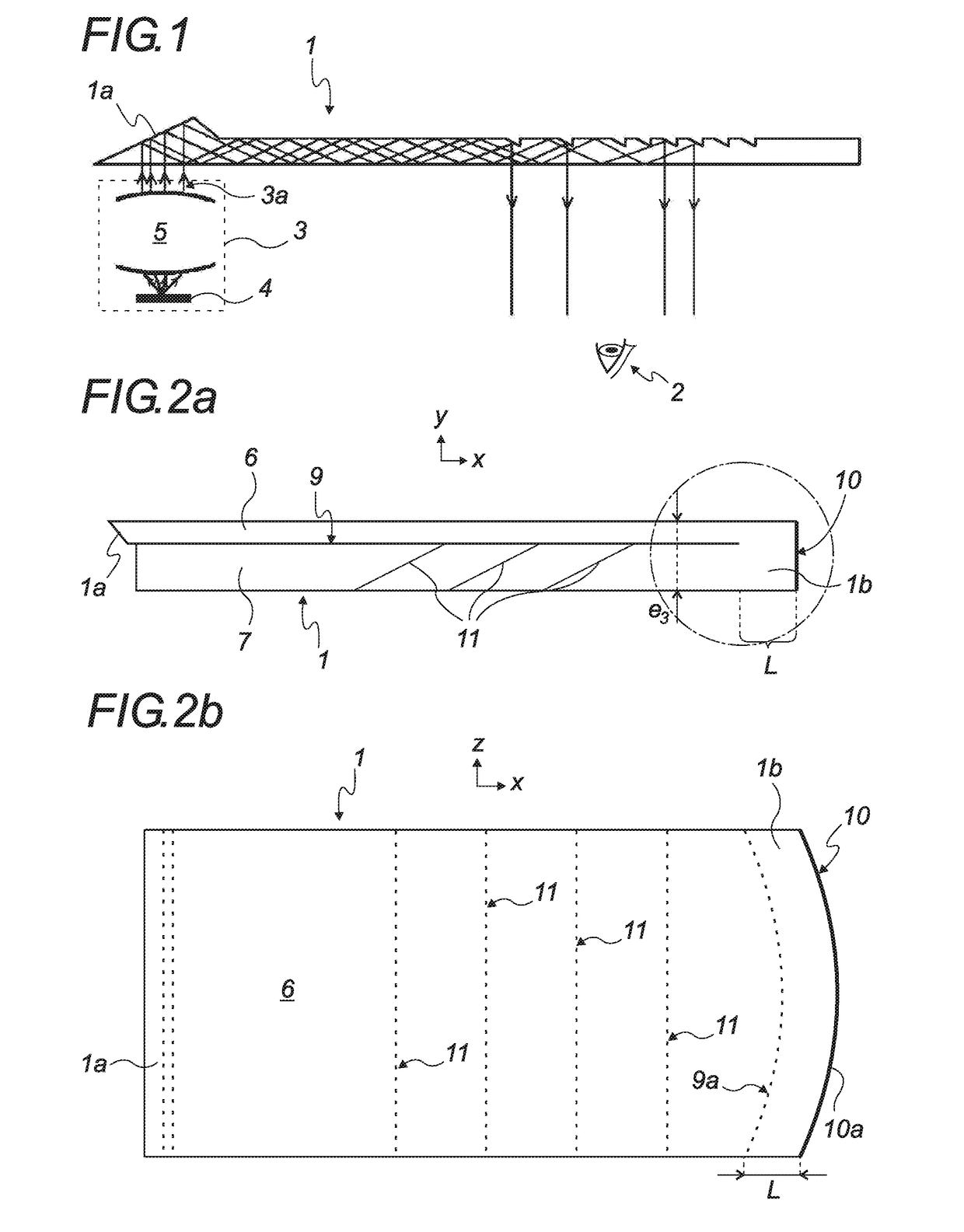
[0058]FIG. 1 very schematically illustrates the general principle of the family of optical guides within which an optical guide 1 is developed.

[0059]These systems therefore comprise an optical guide 1 transporting a beam of light toward an eye 2 of a user.

[0060]The optical system also comprises a light injection system 3, making it possible to inject beams 3a of light into the optical guide 1 via an input zone 1a.

[0061]The injection system 3 comprises a micro-display 4 on which point light sources are located generating the beams of light as well as collimating members 5 making it possible to inject several parallel beams 3a of light in the optical guide 1.

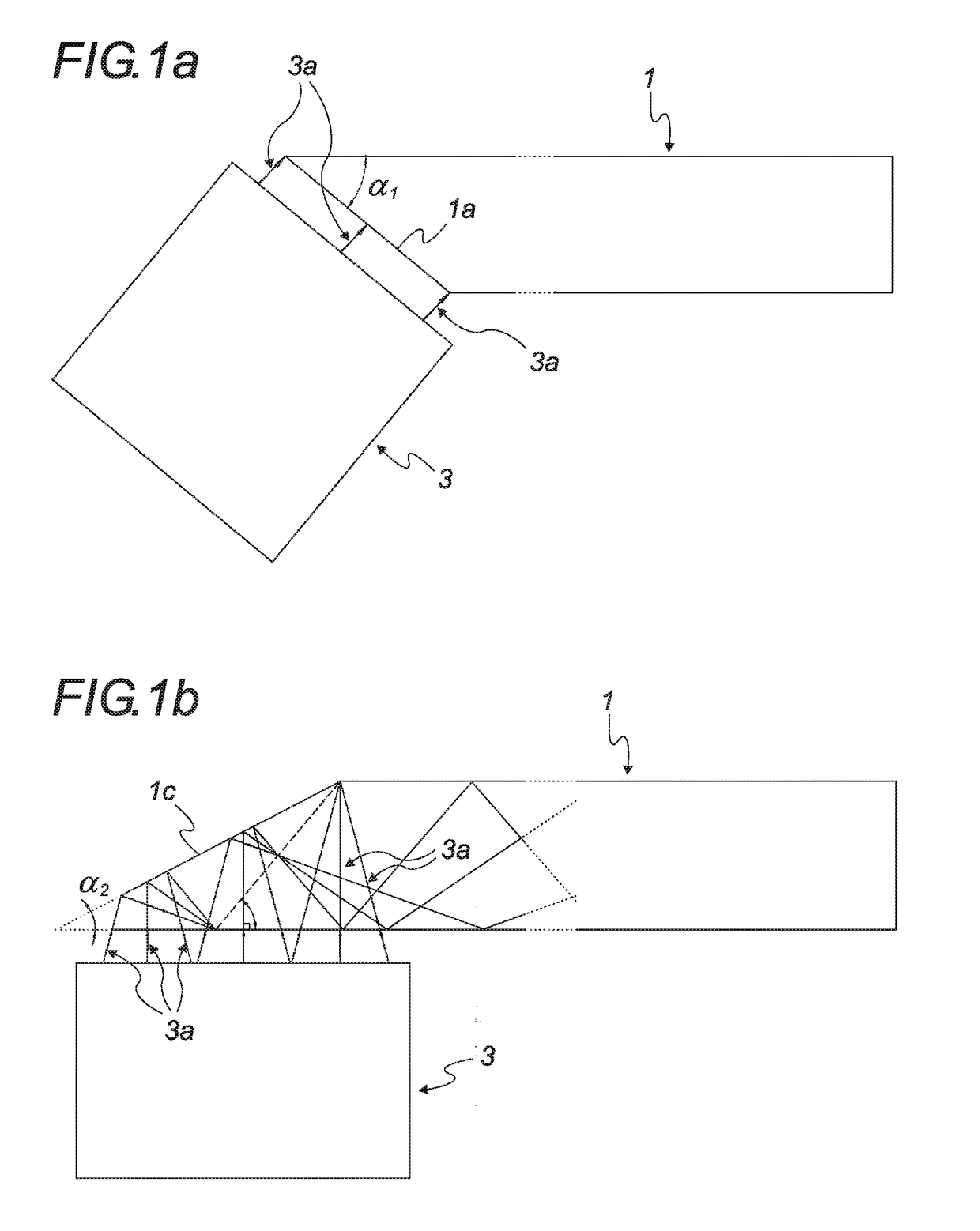
[0062]In the example embodiment illustrated in FIG. 1a, the input zone 1a is an inclined zone of the optical guide 1. The injection of light by the injection system 3 is done by choosing an appropriate angle for the incline of this inclined face.

[0063]In the example embodiment illustrated in FIG. 1b, the injection system 3 is per...


PUM


Abstract

An optical guide for a near-eye display device includes a first guide element having a light input zone and a second guide element having an output zone. The first guide element is superimposed on the second guide element. The optical guide also includes an optical coupling system between the first guide element and the second guide element, and the first and second guide elements have, on the first part of their length, a mutual spacing so as to delimit a thin layer of air between said guide elements extending between a first longitudinal end of the guide elements and the optical coupling system. The optical coupling system, located at a second longitudinal end of the first and second guide elements, includes a single-piece portion of the guide elements, associated with an optical reflection member to propagate the beams of light from the input zone toward the output zone.

Description

TECHNICAL FIELD[0001]The present disclosure relates to the general technical field of optical devices and / or systems used in virtual or augmented reality and, in particular, relates to the medical field, the educational and cultural field, and the gaming field. The disclosure is in particular applicable to navigation, safety, transportation and industrial prototyping systems.[0002]The optical systems according to the disclosure works with all polychromatic or monochromatic light, in the visible domain.[0003]The present disclosure more particularly relates to optical guides used in equipment, accessories or other instruments having a Near-Eye Display (NED), such as helmets or special glasses.BACKGROUND[0004]The known near-eye display devices, in particular those with propagation of light rays in the open air, have non-negligible drawbacks. Indeed, in these devices, the mirrors used are large, thus contributing to increasing the bulk of said devices. The weight of these devices is als...

Claims


Application Information

Patent Timeline
IPC IPC(8): G02B27/01F21V8/00G02B27/09
CPCG02B27/0172G02B6/0066G02B6/0031G02B27/0955G02B27/0977G02B6/0076G02B2027/0123G02B2027/0125G02B2027/015G02B2027/0152G02B2027/0118
Inventor YANG, JIANMINGTWARDOWSKI, PATRICEFONTAINE, JOEL
Owner UNIVERSITY OF STRASBOURG
Why Eureka
Try Eureka