Display device, electronic apparatus, and projection display apparatus

a technology of electronic equipment and display device, applied in the direction of instruments, color television details, optics, etc., can solve the problems of electric current leakage performed forcibly, issue of etc., to suppress the occurrence of temporary burning, suppress the charge up, and suppress the effect of temporary burning

Active Publication Date: 2019-01-31
SONY CORP
View PDF6 Cites 3 Cited by
  • Summary
  • Abstract
  • Description
  • Claims
  • Application Information

AI Technical Summary

Benefits of technology

[0019]According to the display device of the embodiment of the disclosure, the electronic apparatus of the disclosure, and the projection display device of the disclosure, the collapse of symmetry between the voltage application to the common voltage on the positive electrode side and the voltage application to the common voltage on the negative electrode side is moderated in the 1F period, which makes it possible to suppress charge up. As a result, it is possible to suppress occurrence of temporary burning due to precharge. It is to be noted that an effect of the disclosure is not limited to the effects described here, and may be any effect described in the specification.
[0020]In the display device of the embodiment of the disclosure, in a case where the second driver performs the application of the second precharge signal voltage for each of the 1-horizontal periods while the second driver thins the application of the first precharge signal voltage for each of the predetermined horizontal periods, it is possible to suppress the occurrence of temporary burning due to precharge, for any kind of image signal.
[0021]In the display device of the embodiment of the disclosure, in a case where the second driver omits the application of the first precharge signal voltage in the whole or the portion of the horizontal period that includes no application period of each of the image signals, it is possible to reduce deliberate electric current leakage in a blanking period. As a result, it is possible to further suppress the occurrence of temporary burning due to precharge.
[0022]In the display device of the embodiment of the disclosure, in a case where the second driver uniformly assigns, to the application period of each of the image signals, the whole or the portion of the time generated as a result of the thinning of the first precharge signal voltage, even when the above-described collapse of symmetry occurs, it is possible to allow a voltage value of each pixel to approach a desired voltage value by the amount of the application period of the image signal having extended. As a result, it is possible to further suppress the occurrence of temporary burning due to precharge.
[0023]In the display device of the embodiment of the disclosure, in a case where the first precharge signal voltage is the voltage value of the lowest level of the signal voltage or is the voltage value of the level larger than the lowest level thereof, it is possible to further suppress the occurrence of temporary burning due to precharge without deteriorating a reduction effect of vertical crosstalk.
[0024]In the display device of the embodiment of the disclosure, in a case where the second driver performs the application of the first precharge signal voltage and the application of the second precharge signal voltage for each of the 1-horizontal periods, and makes the amplitude of the first precharge signal voltage smaller than the amplitude of the first precharge signal voltage in another horizontal period, for each of the predetermined horizontal periods, similarly to the above-described “thinning”, it is possible to suppress the occurrence of temporary burning due to precharge, for any kind of image signal.

Problems solved by technology

However, electric current leakage is performed forcibly in a two-step precharge system.
As a result, there has been an issue of occurrence of temporary burning.

Method used


Image

  • Display device, electronic apparatus, and projection display apparatus
  • Display device, electronic apparatus, and projection display apparatus
  • Display device, electronic apparatus, and projection display apparatus

Examples


first embodiment

1.First Embodiment

[Configuration]

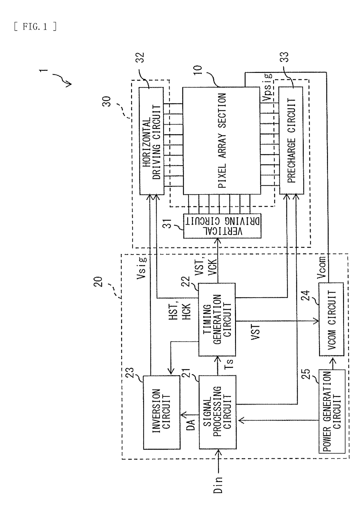
[0080]FIG. 1 illustrates an example of a schematic configuration of a display device 1 according to a first embodiment of the disclosure. The display device 1 is applicable as a light valve of a three-plate projector (a projection display apparatus). The display device 1 includes, for example, a pixel array section 10, a controller 20, and a liquid crystal driver 30. The pixel array section 10 may be of transmissive type or of reflective type. It is to be noted that, in a case where the pixel array section is of transmissive type, the display device 1 may include an unillustrated light source behind the pixel array section 10 as necessary.

(Pixel Array Section 10)

[0081]The pixel array section 10 generates image light by electrically changing a polarization state of light by voltage application. The pixel array section 10 has, for example, transmittance characteristics or reflectance characteristics of normally black. Here, the normally black refers to...

second embodiment

2. Second Embodiment

[0127]FIGS. 25 and 26 each are a waveform diagram for describing an example of the precharge signal voltage Vpsig in a display device 2 according to the second embodiment of the disclosure. In the present embodiment, the controller 20 sets the precharge signal voltage VpsigB to a voltage value of the lowest level (VsigL2, VsigL) of the signal voltage Vsig or a voltage value of a level larger than the lowest level thereof. At this time, as illustrated in FIGS. 25 and 26, the precharge circuit 33 outputs to the signal line DTL the precharge signal voltage VpsigB that is set to the voltage value of the lowest level (VsigL2, VsigL) of the signal voltage Vsig or the voltage value of a level larger than the lowest level thereof on the basis of the control signal supplied from the controller 20, for example. This makes it possible to reduce the amount of the leak of the electric current by the amount of the amplitude of the precharge signal voltage VpsigB having become ...

third embodiment

3. Third Embodiment

[0130]FIGS. 31 and 32 each are a waveform diagram for describing an example of the precharge signal Vpsig in a display device 3 according to the third embodiment of the disclosure. In the present embodiment, the controller 20 controls the precharge circuit 33 in such a manner as to perform the applications of the precharge signal VpsigB and the precharge signal VpsigG (VpsigG1, VpsigG2) for each 1H. The controller 20 further sets the amplitude of the precharge signal VpsigB to a value smaller than an amplitude of the precharge signal VpsigB in another 1H, for each predetermined 1H. At this time, as illustrated in FIGS. 31 and 32, the precharge circuit 33 performs the application of the precharge signal VpsigB and the precharge signal VpsigG (VpsigG1, VpsigG2) for each 1H on the basis of the control signal supplied from the controller 20, and outputs to the signal line DTL the precharge signal VpsigB that is set to have an amplitude smaller than the amplitude of th...


PUM

PropertyMeasurementUnit
polarityaaaaaaaaaa
voltageaaaaaaaaaa
resistivityaaaaaaaaaa

Abstract

A display device according to an embodiment of the disclosure includes a first driver that sequentially selects each of pixels on a row basis, and a second driver that applies, through a signal line, an image signal to each of the pixels in a pixel row that is selected by the first driver, and that inverts a polarity of the image signal at a predetermined period. The second driver sequentially applies, to the signal line, a first precharge signal voltage having a relatively large amplitude and a second precharge signal voltage having a relatively small amplitude, prior to the application of the image signal. The second driver further controls the application of the first precharge signal voltage to cause an amount of leak of an electric current from the pixel to the signal line due to the application of the first precharge signal voltage to become smaller than that in another period for each of predetermined horizontal periods.

Description

TECHNICAL FIELD[0001]The disclosure relates to a display device, an electronic apparatus, and a projection display apparatus.BACKGROUND ART[0002]In a display device including a liquid crystal cell as an electrooptical element, when a DC voltage is continuously applied to the liquid crystal cell for a long time, deterioration of resistivity (a resistance value inherent to a substance) of the liquid crystal, etc., or an afterimage phenomenon called “burning” occurs. Therefore, an AC driving method is adopted which inverts, at a predetermined period, a polarity of a signal voltage applied to a pixel electrode of the liquid crystal cell with respect to an electric potential of a counter electrode of the liquid crystal cell.[0003]As an example of the AC driving method, a 1F inversion driving method is known which, while making constant a common voltage applied to the counter electrode, inverts the polarity of the signal voltage for each 1-field period (1F) or inverts not only the polarit...

Claims


Application Information

Patent Timeline
Patent Type & Authority Applications(United States)
IPC IPC(8): G09G3/36G02F1/1362G02F1/133G09G3/00
CPCG09G3/3614G02F1/136286G02F1/13306G09G3/002G09G3/3648G09G3/3696G09G2320/0257G09G2320/0233G09G2320/0209G09G2310/0251G09G2310/061H04N9/3197H04N9/3105G09G3/20H04N9/312G09G2320/0204
Inventor JINTA, SEIICHIROJINNOUCHI, HIDEO
Owner SONY CORP
Why Eureka
Try Eureka