

Wire-selecting device
- Summary
- Abstract
- Description
- Claims
- Application Information
AI Technical Summary
Benefits of technology
Problems solved by technology
Method used
Image

Examples
first embodiment
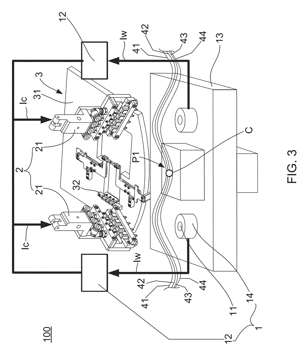
[0050]Please simultaneously refer to FIG. 7A-FIG. 7I, there are a schematic view of a wire-selecting device for wire-selecting action according to the invention. As shown in FIG. 7A-FIG. 7I, First, when the icon core C and the metal wires 41-44 are at the wire-selecting position P1, the image capturing module 11 captures and discriminates the appearance of the metal wires 41-44 to generate the wire appearance information Iw. The wire appearance information Iw has included the position and color of each wire. Therefore, the discrimination module 12 receives the wire appearance information Iw, confirms the position of the metal wires 41-44, and the color thereof, and then generates the wire-selecting control information Ic to the wire-selecting module 2. Then, the wire-selecting control information Ic is transmitted to the wire-selecting module 2, and therefore the s wire-selecting module 2 can be controlled to grip a specific position and a specific appearance of the wire, and the wi...
second embodiment
[0055]According to the technical means employed in the present invention, as shown in the wire-selecting device 100′ of the magnetic element of the second embodiment, the iron core fixing mechanism 22 further comprises two wire clips 223, which are displaceable provided on the core clip 222 Outer sides so that the wire clips 223 are provided on both sides of the iron core C. As shown in Fig. The two wire clips 223 hold the wires 41 to 44, respectively, and the two wire clips 223 are respectively held by a plurality of wires in a direction away from the iron core C to move the plurality of conductors 41-44 are pulled to a preset tension strength. Thereby, it is possible to make the conductive lines 41 to 44 to expand the apparent image pickup module 11 of the identification.
[0056]Referring to FIG. 8-FIG. 11 again, the wire-selecting module 2 further comprising a wires baffle device 224 having a plurality of guide grooves 224a, which used for limiting the plurality of metal wires 41-4...
PUM
| Property | Measurement | Unit |
|---|---|---|
| Thickness | aaaaa | aaaaa |
| Strength | aaaaa | aaaaa |
| Distance | aaaaa | aaaaa |
Abstract
Description
Claims
Application Information