Power switch over-power protection

a power switch and protection technology, applied in the field of integrated circuits, can solve the problems of no provision to protect against over-power conditions, power consumption can increase beyond what is expected from a device under normal operation, and the voltage is larger, so as to reduce the output voltage, increase the voltage of the power mosfet, and reduce the effect of power consumption

Active Publication Date: 2019-01-31
DIODES INC
View PDF0 Cites 10 Cited by
  • Summary
  • Abstract
  • Description
  • Claims
  • Application Information

AI Technical Summary

Problems solved by technology

However, there is often no provision to protect against over-power conditions.
As a result, the power consumption can increase beyond what is expected from a device under normal operation.
The heavier the over current, the larger the voltage, then the higher the power consumption.
Therefore, a constant worst case current limit may be overly restrictive.

Method used


Image

  • Power switch over-power protection
  • Power switch over-power protection
  • Power switch over-power protection

Examples


Embodiment Construction

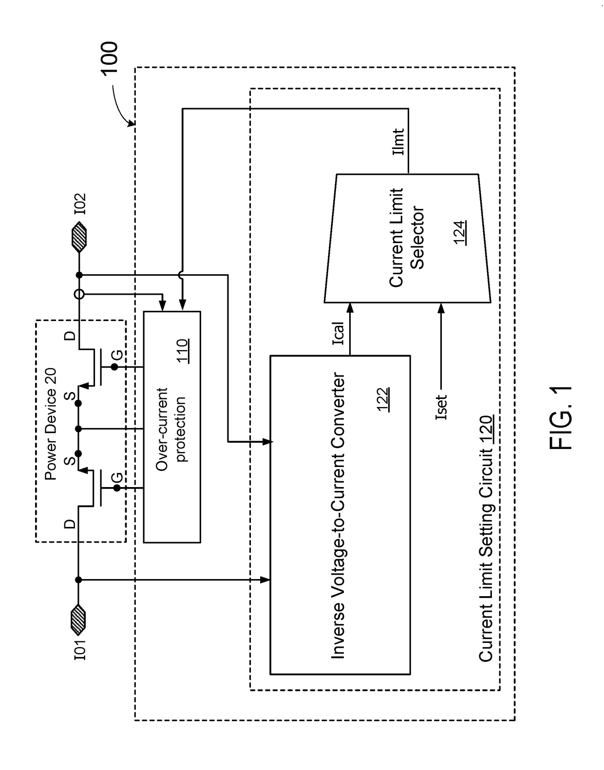
[0035]Electronics devices, such as power MOSFETs, are usually designed to operate within its Safe Operation Area (SOA), which defines, among other things, how long a power MOSFETs can operate with a certain current flowing through it under a certain voltage. In embodiments of the invention, circuits and methods are provided using an over-current protection circuit to also provide over-power protection, i.e., to limit the power consumed in the power MOSFET to within the pre-set maximum power limit to protect the power MOSFET from performance degradation, short life time, and damages.

[0036]In some embodiments, the voltage across a power switch is monitored, and a safe current limit is determined from a power limit. The power limit can be determined, for example, from the Safe Operation Area (SOA) of the device. Given a power limit, the higher the voltage across the device, the lower the allowable current.

[0037]FIG. 1 is a simplified schematic diagram illustrating an over-power protect...


PUM


Abstract

An over-power protection circuit for a MOSFET includes an over-current protection circuit and a current limit setting circuit, and an over-power protection circuit configured to continuously monitor a voltage across the MOSFET being protected to prevent over-power conditions, and to dynamically determine a maximum current limit based on the monitored voltage and a pre-set maximum power limit.

Description

CROSS REFERENCES TO RELATED APPLICATIONS[0001]This application claims priority to U.S. Provisional Patent Application No. 62 / 537,954, filed on Jul. 27, 2017 and entitled “POWER SWITCH OVER-POWER PROTECTION” the disclosure of which is hereby incorporated by reference in its entirety for all purposes.BACKGROUND[0002]The present invention is directed to integrated circuits. More particularly, the invention provides a system and method for over-current protection and over-power protection of a protected device.[0003]In electronic circuits, over-current protection circuits are widely used. In an over-current protection circuit, a power device, e.g., a power MOSFET (Metal-Oxide-Semiconductor field effect transistor), is often used in a protection circuit to protect a load device against over-current conditions. The over-current protection circuit monitors the current flowing through the power device, and compares the measured current with a pre-set maximum allowable current to determine a...

Claims


Application Information

Patent Timeline
Patent Type & Authority Applications(United States)
IPC IPC(8): H03K17/082H03K5/24H03K3/037H02M3/07
CPCH03K17/0822H03K5/24H03K3/037H02M3/07G01R19/255H03K5/26H03K2217/0054
Inventor WU, WEI
Owner DIODES INC
Why Eureka
Try Eureka