Method for Automatic Creation of Cutting Paths in Interior Space of Three-Dimensional Shaped Product

a three-dimensional shaped product and automatic creation technology, applied in the field of automatic creation of horizontal cutting paths in the interior space of three-dimensional shaped products, can solve the problems of inability to automatically create a cutting path in the interior space by a cad/cam system, inability of the cad/cam system to automatically create a program combining the cutting paths of both, and achieve the effect of high-quality interior cutting

Inactive Publication Date: 2019-02-07
MATSUURA MACHINERY
View PDF0 Cites 0 Cited by
  • Summary
  • Abstract
  • Description
  • Claims
  • Application Information

AI Technical Summary

Benefits of technology

[0022]The present invention, as is founded on these basic constructions (1) and (2), specifies the location for a lower region and upper region created by a CAD / CAM system on a conceptually defined imaginary horizontal plane, and the CAD / CAM system can therefore automatically join the lower region and upper region through the specified location, while the programs that create the horizontal cutting paths in both regions can be automatically joined, and so it is unnecessary to further manually create a special program for joining, as is the case of the prior art.
[0023]Moreover, since the lower region and upper region can be joined through the imaginary horizontal plane without any special deformation, it is possible to carry out high-quality cutting of the interior.

Problems solved by technology

For an enclosed interior space of a three-dimensional shaped product, therefore, such as the inner side of a water conduit, it is considered to be impossible to automatically create a cutting path in the interior space by a CAD / CAM system, under a reason that the cutting tool cannot be inserted essentially.
However, in this method, each horizontal cutting path in the upper region and each horizontal cutting path in the lower region are separately and independently created, and as a result it is impossible for the CAD / CAM system to automatically create a program combining the cutting paths of both, since the regions do not have the parameters based on common information.
According to the prior art, therefore, no method has been provided for automatic creation of horizontal cutting paths by a CAD / CAM system for cutting of the interior spaces of three-dimensional shaped products.

Method used


Image

  • Method for Automatic Creation of Cutting Paths in Interior Space of Three-Dimensional Shaped Product
  • Method for Automatic Creation of Cutting Paths in Interior Space of Three-Dimensional Shaped Product
  • Method for Automatic Creation of Cutting Paths in Interior Space of Three-Dimensional Shaped Product

Examples


example 1

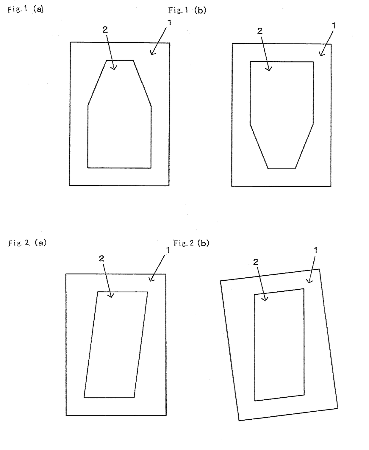
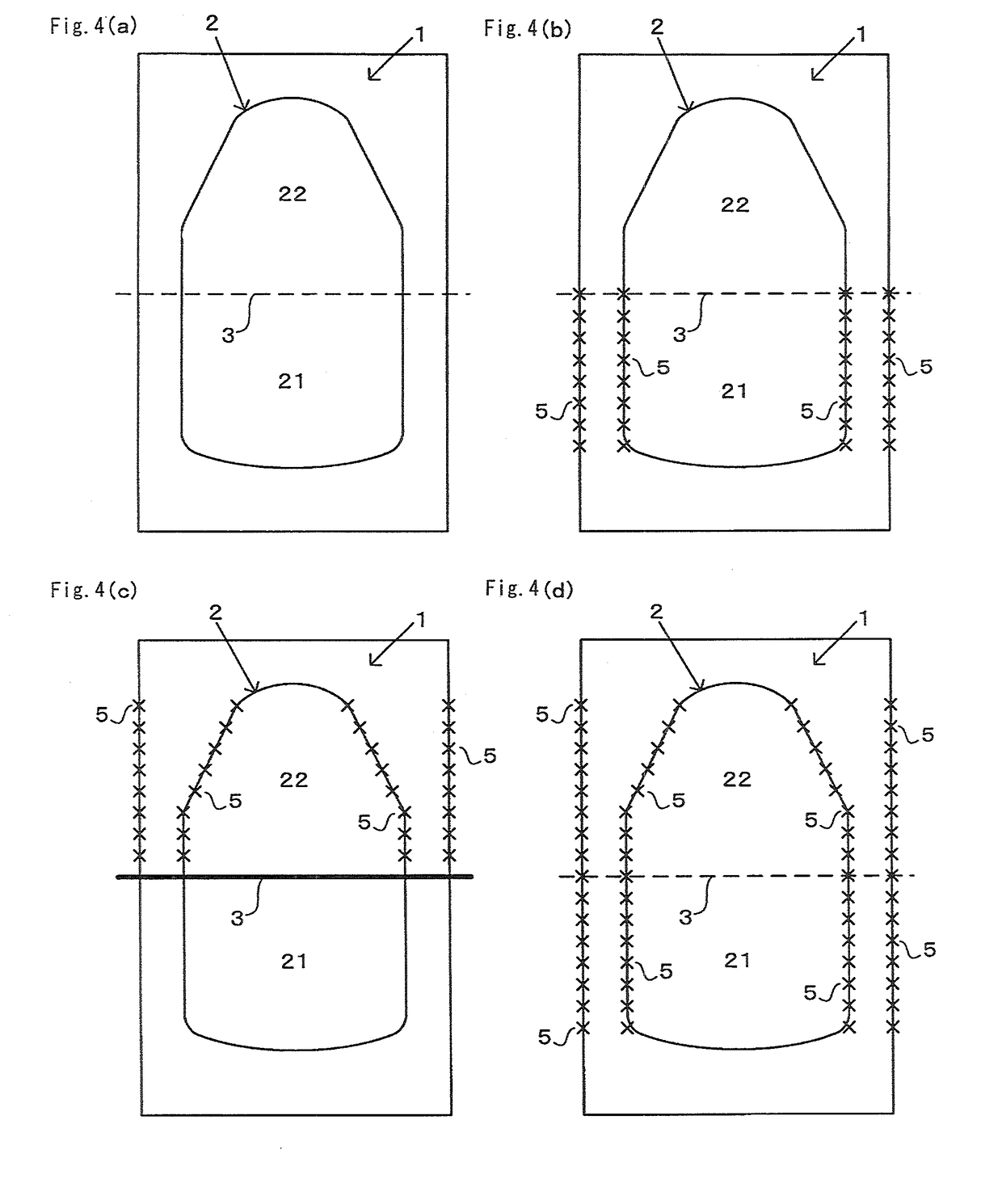
[0059]In Example 1, as shown in FIG. 1, when the shape is comprised in that the horizontal direction width of the interior wall section gradually narrows along the upward direction in a partial region in the vertical direction, while the interior wall section is vertical at the other height regions, the horizontal cutting paths 5 in each of the steps 1, 2, 3 and 4 are created after inverting the upper end locations and the lower end locations.

[0060]In Example 1, a portion of the region along the height direction of the interior wall section narrows toward the upper end, as shown in FIG. 1, and while such a case has conventionally required the use of an undercut tool, since the other regions along the height direction are in the vertical direction, inversion of the lower end and upper end allows a program to be automatically created assuming the use of a standard cutting tool for the horizontal cutting paths 5, thus contributing to more efficient creation of the cutting paths 5.

example 2

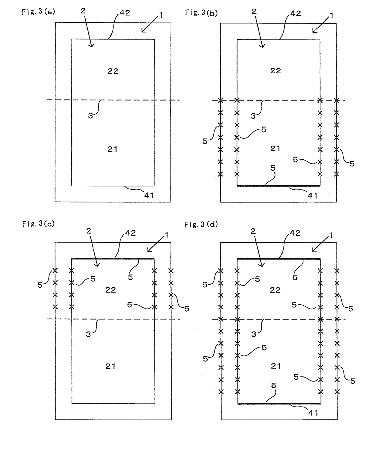
[0061]In Example 2, as shown in FIG. 2, when the facing interior wall sections are parallel slanting state in all of the regions along the vertical direction, the horizontal cutting paths 5 in each of steps 1, 2, 3 and 4 are created after carrying out coordinate transformation from the slanting direction to the vertical direction in all of the regions of the three-dimensional shaped product 1.

[0062]The use of an undercut tool for slanted interior wall sections has conventionally been unavoidable, but in Example 2, the mutually facing interior wall sections are slanted in a parallel manner along the height direction, and therefore by coordinate transformation with an angle shift so that the direction of inclination is vertical, therefore it is possible to create the cutting paths 5 with the premise that a standard tool will be used for all of the regions, thus allowing the cutting paths 5 to be created in a more efficient manner.


PUM

PropertyMeasurementUnit
cutting widthaaaaaaaaaa
distanceaaaaaaaaaa
widthaaaaaaaaaa

Abstract

A method for automatic creation of cutting paths 5 in the interior space 2 of a three-dimensional shaped product 1 by the following steps, in a CAD/CAM system in which programs are designed for lamination, sintering and cutting that are necessary for creating a three-dimensional shaped product 1: defining an imaginary horizontal plane 3, creating cutting paths 5 in the interior wall section from the lower end successively toward the upper side, creating cutting paths 5 in the interior wall section toward the upper side to the upper end, and joining the cutting paths 5 of step 2 and the cutting paths 5 of step 3.

Description

TECHNICAL FIELD[0001]The present invention relates to a method for automatically creating horizontal cutting paths in the interior space of a three-dimensional shaped product, using a CAD / CAM system in which a program is designed for each of the steps of: laminating a powder using a squeegee, sintering by irradiation of a laser beam or electron beam, and cutting by traveling of a cutting tool, that are necessary to produce a three-dimensional shaped product.BACKGROUND ART[0002]When creating a cutting path for a cutting tool by a CAD / CAM system, it is assumed that the regions containing the cutting path are regions in which the cutting tool can be inserted.[0003]For an enclosed interior space of a three-dimensional shaped product, therefore, such as the inner side of a water conduit, it is considered to be impossible to automatically create a cutting path in the interior space by a CAD / CAM system, under a reason that the cutting tool cannot be inserted essentially.[0004]In light of t...

Claims


Application Information

Patent Timeline
Patent Type & Authority Applications(United States)
IPC IPC(8): B29C64/393B29C64/153B33Y10/00B33Y40/00
CPCB29C64/393B29C64/153B33Y10/00B33Y40/00G05B19/4097G05B2219/31427B33Y40/20G05B19/4099G05B2219/35106G05B2219/35107G05B2219/49335G05B2219/49021Y02P90/02
Inventor TARUMI, SATORUKOBAYASHI, JUN
Owner MATSUURA MACHINERY
Why Eureka
Try Eureka