High frequency oscillator, high frequency welding system and method for controlling the frequency using said type of high frequency oscillator

Inactive Publication Date: 2019-02-07
KIEFEL GMBH
View PDF0 Cites 0 Cited by
  • Summary
  • Abstract
  • Description
  • Claims
  • Application Information

AI Technical Summary

Benefits of technology

[0008]The problem underlying the invention is thus to eliminate the disadvantages of the prior art and in particular to prov

Problems solved by technology

However, these high frequency oscillators have relatively low frequency stability, i.e. a low quality factor.
However, in case of rapid load changes, the frequency correction cannot happen at sufficiently short notice.
In particul

Method used


Image

  • High frequency oscillator, high frequency welding system and method for controlling the frequency using said type of high frequency oscillator

Examples


Embodiment Construction

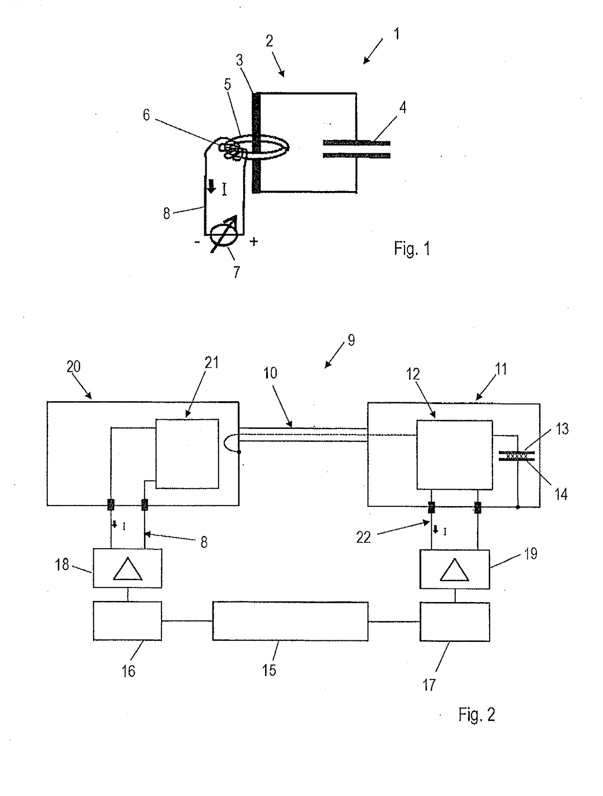
[0025]FIG. 1 shows a schematic diagram of a high frequency oscillator 1 comprising an electric resonant circuit 2. In the electric resonant circuit 2, the electronic component 3 that provides an inductance L is a coil. In addition, the resonant circuit comprises a capacitor 4 having a capacitance C. In its structural principle, the resonant circuit is a conventional LC resonant circuit. In this example, the electronic component 3 is designed as a coil with at least one copper tube. However, it is also possible to provide several coils as well as several capacitors.

[0026]The electronic component 3 is passed through a ring 5 made of a ferromagnetic material, around which a magnetic coil 6 is wound. The magnetic coil 6 is integrated in a control circuit 8 that comprises a controllable direct current source 7.

[0027]Through appropriate actuation of the direct current source 7, the magnetic coil 6 generates a magnetic field, which is superimposed on the field of the electronic component 3...


PUM

PropertyMeasurementUnit
Electrical inductanceaaaaaaaaaa
Frequencyaaaaaaaaaa
Electric impedanceaaaaaaaaaa

Abstract

A high-frequency oscillator includes an electric resonant circuit, and a high-frequency welding system and a method for controlling the frequency uses a high-frequency oscillator, in particular in a high-frequency welding system. The electric resonant circuit includes at least one electronic component having an inductance and at least one capacitor having a capacitance. At least one additional magnetic coil is associated with the electronic component and can electronically influence the inductance of the electronic component.

Description

CROSS REFERENCE TO RELATED APPLICATIONS[0001]This application is a divisional of and Applicant claims priority under 35 U.S.C. §§ 120 and 121 of U.S. application Ser. No. 14 / 787,309 filed on Oct. 27, 2015, which application is a national stage application under 35 U.S.C. § 371 of PCT Application No. PCT / DE2014 / 000176 filed on Apr. 8, 2014, which claims priority under 35 U.S.C. § 119 from German Patent Application No. 10 2013 008 730.9 filed on May 24, 2013 and German Patent Application No. 10 2013 021 062.3 filed on Dec. 18, 2013, the disclosures of each of which are hereby incorporated by reference. A certified copy of priority German Patent Application No. 10 2013 008 730.9 and a certified copy of priority German Patent Application No. 10 2013 021 062.3 are contained in parent U.S. application Ser. No. 14 / 787,309. The International Application under PCT article 21(2) was not published in English.BACKGROUND OF THE INVENTION1. Field of the Invention[0002]The invention relates to a h...

Claims


Application Information

Patent Timeline
IPC IPC(8): B29C65/00B29C65/08H03J3/22H03B5/12
CPCB29C66/9512B29C65/08H03J3/22B29C66/95H03B5/1256B29C65/04H03J3/16H03B5/08H03B1/02H01P1/217H03J3/20
Inventor MARTINEZ VELA, FERNANDO
Owner KIEFEL GMBH
Why Eureka
Try Eureka